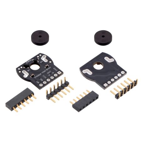
Paire d'encodeur rotatif pour Romi - CPR 12
2x rotatif encoder for Romi robot
- Magnetic quadrature encoder
- CPR 12 - count = 12 per motor shaft rotation
- Supply voltage 3.5 a 18V
Payments are secured by LyraCollect, a French payment collection company.
It is possible to delivered to your home, to a pick-up point or picked up by appointment at MCHobby
We prepare, pack and ship your orders with great respect and care.
Add a quadrature encoder on the gearmotor of your Romi robot
This quadrature encoder kit includes two dual-channel Hall effect sensor and 6-pole magnetic discs (named CPR discs) used to add quadrature position reading on Romi chassis mini plastic gearmotors.
The encoder board senses the rotation of the magnetic disc and provides a resolution of 12 counts per revolution of the motor's shaft. Note that electronics must count both edges (raising and falling) of both channels to get the complete resolution which corresponds to approximately 1440 counts per revolution of the Romi’s wheels.
This kit offer a really compact encoder solution fiting within the 11.5 mm × 22.5 mm cross section of the rear of the motors on three of the four sides. The last side of the encoder board has connections for signal power (it extends 7 mm past the edge of the motor).
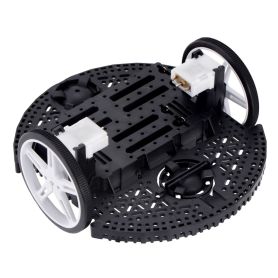
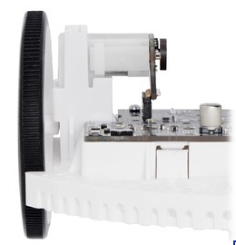
As designed, the encoder board are at the right height to be able to plug it into a board mounted on the Romi chassis (see the picture below). The final assembly (motor + encoder + CPR disc) does not extend past the end of the extended motor shaft (so 5 mm beyond the back of the motor).
Pinout and installation
The encoder board is designed to be soldered directly to the back of the motor, with the back shaft of the motor protruding through the hole in the middle of the circuit board. One way to achieve good alignment between the board and the motor is to tack down the board to one motor pin and to solder the other pin (M1, M2, VCC, OUTA OUTB, GND) on en encoder only when the controler board and the motor are well in place (flat and well aligned).
Currently it exist two boards that natively supports the encoder: the Romi 32U4 Control Board and the "Motor Driver and Power Distribution Board" for Romi Chassis. The encoder pins needs to be installed pointing down toward the chassis in order to be able to plug into this board.
For robots using custom made board (or no using any board but microcontroler), it might be more convenient to install the board and pins facing up to connect to them with cables made from our wires with crimped terminals (6 connectors).
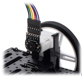
Note: it is possible to remove the motor from the ROMI chassis and rotate it (180°) and plug it back on the chassis. Such way, you can have to connector pointing up or pointing down (as you wish it).
Once the board is soldered down to the two motors terminals, the motor can be powered throught the M1 and M2 connection available along the edge of the board; the other pads VCC & GND are used to power the sensors and AOUT A & OUT B access the two quadrature outputs:
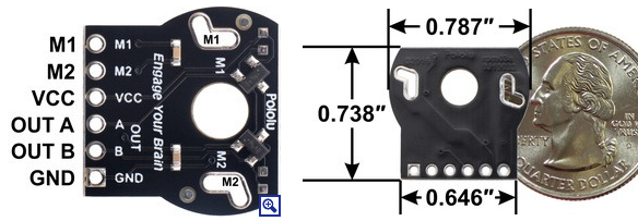
The sensors are powered through the VCC and GND pins. VCC can be 3.5 V to 18 V, and the quadrature outputs A and B are open-drain digital signals that need to be pulled up to the appropriate logic voltage of your system. The encoder boards have pads for optional 0603 size surface-mount resistors to pull the outputs up to VCC. Microcontroler typically have internal pull-up resistors that can be activated by code.
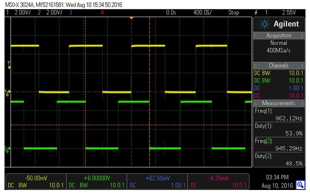
Output A and B from CPR encoder

