


Two relay module
Control module with TWO relays ready to use

Payments are secured by LyraCollect, a French payment collection company.

It is possible to delivered to your home, to a pick-up point or picked up by appointment at MCHobby

We prepare, pack and ship your orders with great respect and care.
Un dual relais module with high quality relais perfect for 5V & 3.3V logic
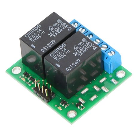
Here is a module with TWO relays for Arduino ready to use for your projects based on micro-controllers.
This module provides all the necessary features for a fast implementation but especially two Omron G5LE-14-DC5 relays capable of supporting a current of 10A in most cases.
Practical, it will offer a galvanic isolation (the high-voltage circuit is never in contact with the control circuit) allowing the control of more powerful devices (such as a fan, a small water pump, a low power motor, etc).
Description
Pololu's dual-directions dual-relay module allows independent and easy control of the equivalent of unipolar commutators (so-called "single-pole") two directions (so-called "double-throw") from a low signal voltage and low control current. These relays are called "SPDT" for "single pole double throw".
This module uses 5V powered relays type Omron G5LE-14-DC5 (1Mb, pdf) and the card is fully assembled.
The card is equipped with standard 2.54mm impaction pins (like breadboards) which allows you to take control of the card with 3-pin Molex connectors or suitable connectors (see our wire assortment). Relay power contacts are routed to 5mm 3-way terminal blocks.
The card is equipped with 4 mounting holes for M3 screws.
Technical characteristics
- Compact module.
- Indicator LEDs for relay status.
- Use of Zener diode to decrease the current in the coil faster.
- Tracking routing rules and node for electrical equipment (regulation US).
- Omron G5LE Relay data sheet (pdf)
- Possibility of placing a standard jack plug (DC power supply, optional).
- Scheme of the module (pdf)
- With relay power supply VDD=5V
- Activation current with signal 5V = 0.040mA
- Activation current with signal 3.3V = 0.030mA
Use the module

The relay commutator part is accessed from one side of the card while the control pins are routed to the opposite side of the card. The relay coil is powered at 5 Volts using the VDD and GND pins and the relay is activated by a high signal on the ENx control pin. The control signal directly drives a BSS138 N-channel MOSFET. When the voltage on the ENx control pin exceeds about 2.5V, this activates the relay coil (see the BSS138 data sheet, 92k pdf).
The control pins are placed so that it is possible to use either a 4-pin connector or two 3-pin connectors. In this way, it will be possible to power the module and to provide the activation signals.
- When the relay is activated: the power contact is between the COMx (common) and NO (Normally open) pins.
- When the relay is not activated: the power contact is between the COMx and NCx (Normally closed) pins.
The COM (common), NO ("normally open") and NC ("normally closed") power pins are routed to the PCB with 1.5mm minimum spacing between tracks but also to the edge of the map.
In most applications, the voltage and current limits of the module will match the relays used on the card. The maximum current, the maximum voltage and the time life of the relay are interdependent; it is therefore very important to carefully examine the relay's data sheet.
High voltage use
This product has not been designed and does not have certification for high voltage use. Working with a voltage higher than 30V can be extremely dangerous and should be reserved for people who are qualified to work in such conditions. It is necessary to use an appropriate equipment and to apply adequate safety rules.
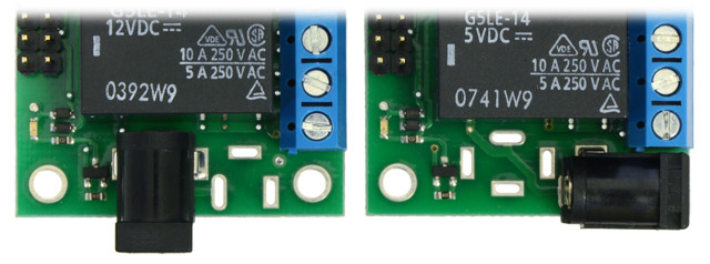
Jack connector
It is possible to add a Jack connector (optional) to supply DC relays. The picture below shows two of three possible configurations. The third configuration allows to place this connector under the card.