


12V 2A, Step Up/Down regulator, S18V20F12
S18V20F12 DC/DC regulator
- Step-Up/Down
- Input: 3 to 30V
- Output: 12V
- jusqu'à 2A

Payments are secured by LyraCollect, a French payment collection company.

It is possible to delivered to your home, to a pick-up point or picked up by appointment at MCHobby

We prepare, pack and ship your orders with great respect and care.
Obtain 12V (2A) output voltage from higher or lower voltage and the S18V20F12
The S18V20F12 step-up/step-down switching voltage regulator efficiently produces 12 volts from a 3-30V power source with a typical current of 2 amps. These switching regulators are commonly referred to as DC-to-DC regulators, Switched Mode Power Supplies (SMPS), or switching regulators.
It has the ability to convert lower (step-up) and higher (step-down) voltages, making the breakout very useful for applications where voltage can widely fluctuate. You can therefore use it in designs where the starting voltage is above 12 volts and then drops below 12 volts (after discharging your power source). This module is quite compact (4.3cm x 2.1cm) and has an efficiency between 80% and 90%.
Step-up, Step-Down... what does it means?
Step-Up is an English term that we translate as "increase". While Step-Down will be translated as "decrease". These are characteristics of switching voltage regulators.
A step-up regulator is capable of increasing the input voltage to reach the desired output voltage. A step-down regulator will be able to handle a higher input voltage to reach the desired output voltage.
A step-up/step-down regulator is able of reaching the desired voltage from a lower or higher supply voltage.
This model is useful if you need to keep a project powered for as long as possible with a power source whose voltage drops over time (e.g., a battery).
Description (following)
The flexibility of input voltage supported by this regulator makes it particularly well suited for battery-powered projects where the voltage is generally higher than the desired voltage but gradually drops below the desired voltage as the battery is depleted. If you have no restrictions on the minimum voltage during the life cycle of your batteries then you can consider new approaches (different battery packs, lighter, different form-factor). For example:
- 4 batteries pack, which allows to obtain an output voltage of 6 V with 4 brand new alkaline batteries.
Important note: 4 NiMH batteries would only give 4.0V with partially discharged batteries, this is not suitable for the 12V regulator because it will requires lots of current to step-up the voltage to 12V. However, this would be great for 5V output regulation. - A 9V (disposable) battery would not be suitable for this purpose because its voltage would drop too quickly.
If you need 12 volts and a current of 1 amp, your project is a power-hungry project. It's important to know that 9-volt batteries aren't designed for high-power projects... but rather to ensure the long-term survival of low-power projects. A 9-volt battery is more suitable for a 5-volt step-up/step-down regulator (which, in turn, accepts a minimum voltage of 3 volts).
The no-load leakage current typically ranges between 1 mA and 5 mA for all input and output voltage combinations (e.g., the leakage current of the 12V version of the regulator is approximately 4 mA with a 3 V input voltage, 1.5 mA with a 12 V input voltage, and 1 mA with a 30 V input voltage).
The ENABLE pin can be used to place the regulator in a power-saving mode, which reduces the leakage current to approximately 10 - 20 µA per volt of input voltage on VIN (e.g., approximately 30 µA with Vin = 3 V and 500 µA with Vin = 30 V).
This regulator features reverse voltage protection, over-current protection, and thermal protection (cutoff at 165°C).
The regulator also features under-voltage protection; this protection disables the regulator when the input voltage drops below 2.5V (typically).
Technical details
- Input voltage (Vin) : 2.9 V to 32 V
32V is the absolute maximum; We recommend a maximum supply voltage of 30V (which is the limit voltage for reverse polarity protection). - Output voltage at 12 V (4% accuracy).
- Maximum current of 2 A (typical and continuous). When the input voltage is close to the output voltage.Note that the efficiency and maximum output current depend on the voltage difference between input and output (see graphs)
- Protection against reverse polarization (up to 30 V), over-current, overheating (by cutting off) and under-voltage (by disabling the converter).
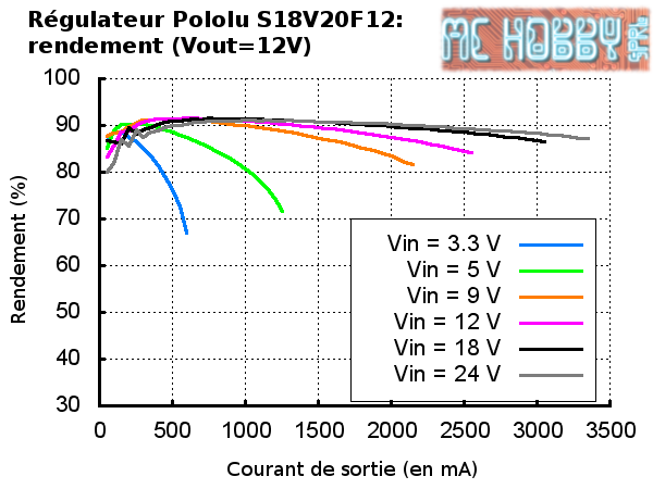
- Efficiency of 80% to 90%, depending on input voltage, output voltage and load (current)
- 4 mounting holes for M2
- Compact: 43 × 21mm. Height 10 mm
- 2.54mm spacing holes (for pin header installation) or larger holes for terminal block installation. This gives you multiple connection options in your projects.
Using the regulator
Connecting
The regulator has 3 main connections labeled on the back of the board:
- VIN: input voltage.
- GND: ground.
- VOUT: output voltage.
- Enable: Allows you to enable/disable the regulator.
The connections are available in 2.54mm spacing, which is ideal for using the board with breadboards and prototyping boards. BUT YOU CAN ALSO CONNECT TERMINAL BLOCKS to the holes provided for this purpose.
The input voltage, VIN, should be between 2.9 V and 32 V. A lower input voltage will cause the regulator to lock up so that it does not operate unpredictably; a higher input voltage will cause the regulator to destroy itself, so you must ensure that the noise on the voltage source is not excessive (e.g. in a car there can be surges of up to 60 volts). 32 V should be seen as an absolute maximum limit. We recommend a maximum voltage of 30 V.
The regulator is enabled by default: a 100 kΩ pull-up resistor is integrated on the board. This pull-up resistor connects the ENABLE input to the VIN pin (protected against reverse bias). The ENABLE pin can be pulled low (to ground, below 0.7 V) to put the board in power saving mode. The leakage current in this more is dominated by the current flowing through the pull-up resistor (between ENABLE at ground and the voltage applied to VIN and the reverse bias protection circuit), this current is of the order of 10 µA to 20 µA per volt applied to VIN while ENABLE is held low (e.g. approximately 30 µA with 3 V on Vin and 500 µA for 30 V on Vin). If you do not need this functionality then you should leave the ENABLE pin disconnected.
Note that the SEPIC topology implements capacitors between the input and output; therefore, the output is not completely disconnected from the input when the regulator is disabled.
Efficiency and output current
Voltage regulator efficiency is defined as (Output Power)/(Input Power). This is an important metric for evaluating performance, especially if battery life or heat dissipation are critical to your project. As the graph below shows, this regulator has an efficiency between 80% and 90%.
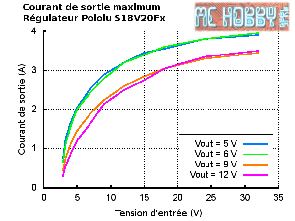
The maximum achievable output current of the board varies with the input voltage but also depends on other factors, including the ambient temperature, air flow, and heat sinking. The graphs below show output currents at which this voltage regulator’s over-temperature protection typically kicks in after a few seconds. These currents represent the limit of the regulator’s capability and cannot be sustained for long periods, so the continuous currents that the regulator can provide are typically several hundred milliamps lower.
Warning it may may burn
During normal operation, this product can get hot enough to burn you. Take care when handling this product or other components connected to it.
Surge spikes caused by LC circuits
When you connect voltage to an electronic circuit, the initial current draw can cause a surge that can be much higher than the input voltage. The regulator can be destroyed if these surges exceed the maximum allowed voltage. IF you connect a power supply of about 9V (and higher), or use connection wires exceeding 5 cm, or use a power supply with a high inductance THEN we recommend soldering a 33 μF capacitor or large electrolytic capacitor near the regulator between VIN and GND. The capacitor must be able to withstand a voltage of at least 16 V.
You can find more information on LC surges in the Pololu application notes see "Understanding Destructive LC Voltage Spikes".
")