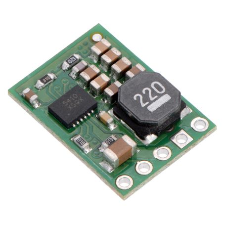


3.3V 1A DC/DC regulator, Step Down, D24V10F3
Switching regulator D24V10F3, 3.3V 1000mA, Step-Down

Payments are secured by LyraCollect, a French payment collection company.

It is possible to delivered to your home, to a pick-up point or picked up by appointment at MCHobby

We prepare, pack and ship your orders with great respect and care.
Get a voltage of 3.3V 1A from a higher voltage source thanks to the D24V10F3
The D24V10Fx family of voltage regulators are step-down regulators using an ISL85410 Interstil component. It is able to produce a voltage of 3.3V from a power source up to 36V. These switching regulators are commonly called DC-to-DC regulator, Switched Mode Power Supply (SMPS) or switching regulator.
This regulator has an efficiency between 80% and 90% and is more efficient than a linear voltage regulator... especially since the voltage difference between the input and output is large. These regulators feature a power-saving mode that allows the regulator to be immersed in a very low-power mode (when there is no charge)... an option particularly suitable for applications that operate with battery.
Warning: this card DOES NOT have reverse polarization protection.
Step-up, Step-Down... What about it?
(Step-Up is an English term that we will translate as "increase". While Step-Down will be translated as "diminish".)
These are characteristics of switching regulators. A Step-up regulator is able to increase the voltage to reach the desired voltage. A Step-Down regulator will be able to handle a higher voltage input to achieve the desired voltage.
A Step-Up/Step-Down regulator is able to reach the desired voltage from a lower or higher supply voltage. The latter model is useful if you need to keep a project running for as long as possible with a power source whose voltage drops over time (ex: battery).
Characteristics
- Input voltage: [output voltage + Drop-Out voltage] up to 36 V
The Drop Out voltage is the voltage loss caused by the regulator. To see further. - Output : fixed to 3.3V accuracy of +4%
- Output current: 1000mA
- Hash frequency: 500 KHz
- Protection against overheating (by breaking) and short circuits.
- Standby current of 200µA (typical when there is no charge).
- "Soft-Start" 2ms to limit current draw when powering up.
- Size: 18 × 13 × 3.5 mm
Use the regulator
During the operation of the regulator, the temperature may become high enough to burn you. Be careful when handling this product and those connected to it.
Connection
The regulator has 5 denominated connections on the back of the card:
- VIN: input voltage.
- GND: ground.
- VOUT: output voltage.
- nSHDN: (reverse logic) Shutdown is used to switch the card to save power.
- PG: output voltage OK.
The connections have an impaction of 2.54mm, which is ideal for using the card with breadboards and prototyping card. Thanks to the connectors supplied with the card, you can weld the regulator against the card or perpendicularly (to save space).
nSHDN: The nSHDN pin can be set low (below 0.3V) to disable the output and put the card in a power saving mode. There is a pull-up resistor of 100 kΩ between the SHDN and VIN pin. Therefore, if you want the card to be constantly enabled, leave this pin disconnected. When the pins are placed at the low level, the current consumed by the regulator is mainly determined by the current through the pull-up resistor and will therefore be proportional to the VIN input voltage (at 36V, the current is approximately 360µA).
VIN: The input voltage should be between 3 and 36V. But the latter must be greater than VOUT + the voltage drop-out (voltage drop of the regulator, see the graph of the voltage drop-out depending on the charge). Also be careful with the over-voltage spikes of LC circuits (see note).
PG: is the "power good" indicator, is an open drain output that goes low when the regulator voltage drops below 80% or above 120% of the expected output voltage. This pin is also actively maintained at the low level during the 2ms needed for soft-starts of the regulator and when the regulator is deactivated by the SHDN input or in the conditions of over-current and overheating. An external pull-up resistor is needed when you want to use this pin.
VOUT: The output voltage is set by the regulator model. The D24VxF3 version produces 3.3V output, the D24VxF5 version produces 5V, the D24VxF9 version produces 9V and the D24VxF12 version produces 12V.
Efficiency and output current
The efficiency of the voltage regulator is defined as "output power" / "input power". This is an important measure of performance, especially if battery life or heat generation are critical to your projects. As shown in the graph below, this regulator has an efficiency between 85% and 95%. The power saving characteristics make it possible to maintain this very high efficiency even when the current is very low.
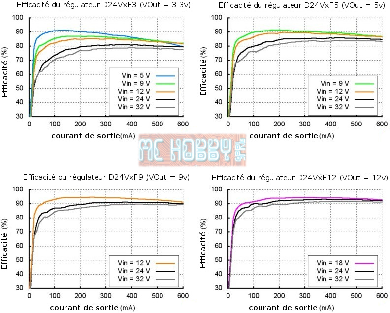
The maximum current that can be obtained from the card depends on the regulator model. You will not be able to get more than 300mA from the 300mA regulator, 600mA for the 600mA regulator and 1A for the 100mA regulator.
Typical voltage drop (Drop-out voltage)
The voltage drop of a Step-Down regulator is the minimum amount of voltage that must be added to the VIN input. This voltage drop is also called Drop-Out voltage.
See the green arrow in the graphs below. If you use a 5V regulator: the input voltage must be at least 5V + 1.1V (6.1V) for a D24VxF5 (5V output) delivering a current of 200mA.
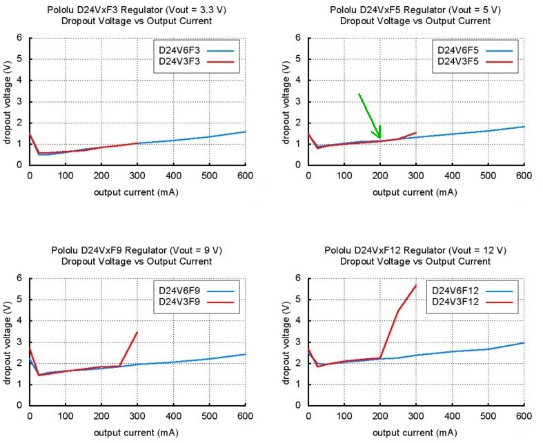
You can see on the last two graphs that the 300mA regulators (9 and 12 V) have a drop-out voltage which really becomes very important when one approaches the 300mA. On the other hand, the 600mA version of the same regulator (blue curve) has a much better controlled voltage drop and remains more stable.
Over-voltage spikes caused by LC circuits
When you connect the voltage to an electronic circuit, the initial current draw can cause an over-voltage spikes that can be much higher than de input voltage. The regulator may be destroyed if these over-voltage spikes exceed the maximum permitted voltages. If you are using connection wires of about 50cm and connect a power supply of about 20V then you could get over-voltages per LC circuit that can exceed 42V. If you are using a power supply of more than 20V or a high inductance power supply, we recommend welding a capacity of 33µF or large electrolytic capacity near the regulator between VIN and GND. The capacity must be able to support a voltage of at least 50V.
More information on LC over-voltages can be found in the pololu application notes, see "Understanding Destructive LC Voltage Spikes".
