


5V 500mA DC/DC regulator, Step Up/Down, S7V7F5
Switching regulator S7V7F5, 5V 500mA, Step-Up/Down

Payments are secured by LyraCollect, a French payment collection company.

It is possible to delivered to your home, to a pick-up point or picked up by appointment at MCHobby

We prepare, pack and ship your orders with great respect and care.
Transform a power source to 5V efficiently with this DC/DC regulator
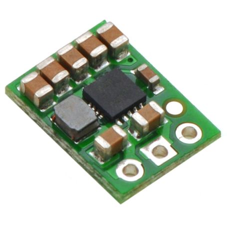
The S7V7F5 step-up/step-down switching voltage regulator produces a voltage of 5V from a power source between 2.7V and 11.8V. These switching regulators are commonly called DC-to-DC regulator, Switched Mode Power Supply (SMPS) or switching regulator.
It has the ability to convert lower voltages (step-up) and higher (step-down), making breakout very useful for applications where voltage can vary greatly. You can use it in mounts where the starting voltage is greater than 5 volts and then drop below 5 volts (after discharge of your energy source). This module is very compact (0.89cm x 1.2cm) and has an efficiency greater than 90% and can deliver up to 1A in Step-Down (decreasing the voltage at 5 volts) and about 500mA in Step-Up (by increasing the voltage up to 5V).
Step-up, Step-Down... What about it?
These are characteristics of switching regulators. A Step-Up regulator is able to increase the voltage to reach the desired voltage. A Step-Down regulator will be able to handle a higher voltage input to reach the desired voltage.
A Step-up/Step-down regulator is able to reach the desired voltage from a lower or higher supply voltage. The latter model is useful if you need to keep a project running for as long as possible with a power source whose voltage drops over time (for example: battery).
Description (following)
This input voltage flexibility is a practical advantage for battery-based applications where the voltage at the start of operation is above 5V and drops as the battery discharges. Without this constraint to have batteries that absolutely must keep a minimum voltage throughout its life, it is possible to consider the use of other type of "battery pack" or battery format more appropriate with the congestion constraints of your project. For example, with a support of 4 batteries we get 6 volts output with brand new alkaline. If you replace the alkaline with NiMH batteries, we get a nominal voltage of 4.8V which drops to 4.0V when partially discharged. With this regulator, you can use your mount with both type of batteries... your circuit will be powered by 5V. Another scenario is the use of a disposable 9V battery to power a 5V circuit. These batteries can discharge to less than 3V. Using a standard regulator (like your Arduino), your mount will stop working when the battery voltage drops to 6V, with this regulator the 9V battery will discharge to at 3 volts while your mount still has its 5 volts.
In the typical application setting, the regulator is able to deliver 1A continuously if the input voltage is greater than 5V (Step-Down operation) and 500mA continuously when the input voltage is below 5V (Step-Up operation). See the graph for more detailed information on this feature. The regulator has a short-circuit protection and a thermal safety protecting the circuit against overheating (by breaking). The card has no protection against reverse polarization.
Characteristics
- Input voltage: 2.7 V to 11.8 V
- Output: fixed at 5V accuracy of +5/-3%
- Output current:
- 1 A in step-down operation (input voltage greater than 5v).
- 500 mA in step-up operation (input voltage at 5 volts)
- The really available output current depends on the input voltage. See the information in the "Efficiency and output current" section below.
- Energy saving mode that maintains another low current performance (idle current is less than 0.1mA)
- Protection against overheating (by breaking) and short-circuits.
- Size: 9 × 12 × 3 mm
Use the regulator
During the operation of the regulator, the temperature may become high enough to burn you. Be careful when handling this product and those connected to it.
Connection
The regulator has 3 connections on the back of the card:
- VIN: input voltage.
- GND: the ground.
- VOUT: output voltage.
The connections have an impaction of 2.54mm, which is ideal for using the card with breadboards and prototyping card. Thanks to the connectors supplied with the card, you can weld the regulator against the card or perpendicularly (to save space).
The input voltage must be between 2.7V and 11.8V. A lower input voltage stops the regulator while voltage higher than 11.8V can destroy it. You must also avoid excessive noise and stay alert for destructive voltage spikes that may be caused by LC circuits.
The output voltage, VOUT, is regulated at the set voltage of 5V. This latter can nevertheless be raised to 5.2V when there is no (or little) load.
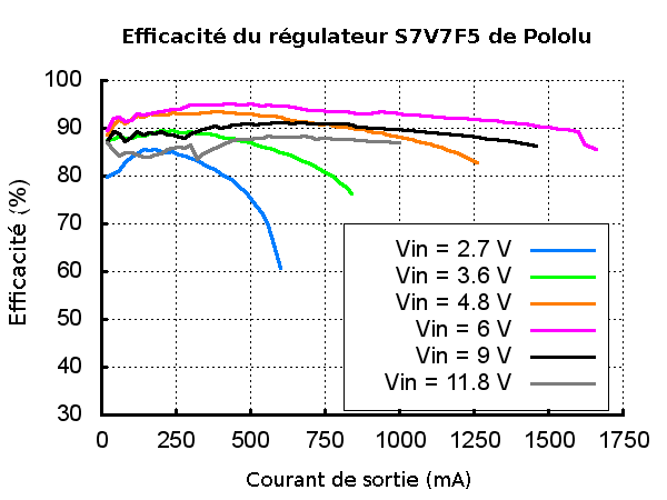
Efficiency and output current
The efficiency of the voltage regulator is defined as (output power)(input power). This is an important measure of performance, especially if battery life or heat generation are critical to your project. As shown in the graph below, this regulator has an efficiency between 85% and 95%. The energy saving characteristics make it possible to maintain this very high efficiency even when the current is very low.
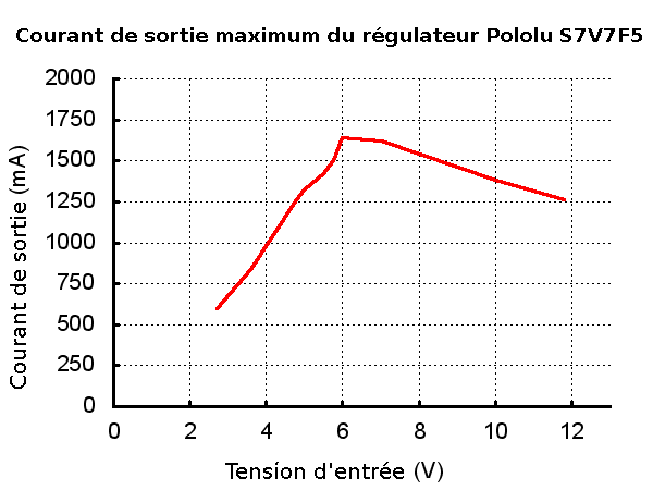
The maximum current that can be obtain from the card depends on the voltage available at the input but also other factors including ambient temperature, air circulation, heat dissipation. The graph below shows the maximum available current for the input voltage given to the regulator (the current at which the regulator's overheat protection trips after a few seconds). These currents represents the limiting capacities of the regulator and can't be maintained for long periods. Therefore the current that the regulator can continuously deliver is several hundred milliAmps below and we recommend not to draw more than 1 Ampere with this regulator (over the available input voltage range).
Overvoltage spikes caused by LC circuits
When you connect the voltage to an electronic circuit, the initial current call can cause a overvoltage spike that can be much higher than the input voltage. The regulator may be destroyed if these overvoltage spikes exceed the maximum permitted voltage. IF you connect a power supply of approximately 9V (and more), or use branch wires exceeding 5cm, or use a power supply with a high inductance THEN we recommend to weld a capacity of 33µF or large electrolytic capacity near the regulator between VIN and GND. The capacity must be able to withstand a voltage of at least 16V.
You will find more information about LC over-voltage in the pololu application notes, see "Understanding Destructive LC Voltage Spikes".