


Breakout connector for Micro:bit
Pre-built Edge Connector Breakout Board for the micro:bit provides access to all the important pins on the bottom edge of the micro:bit.

Payments are secured by LyraCollect, a French payment collection company.

It is possible to delivered to your home, to a pick-up point or picked up by appointment at MCHobby

We prepare, pack and ship your orders with great respect and care.
An extension connector for Micro:bit
Do you want to more with your Micro:bit? Unlock its potential with this Edge Connector Breakout Board! The board has been designed to provide an easy way for connecting additional circuits and hardwares to the Micro:bit (on the pins available between the large pads). With this board you will gain accès to all the micro:bit's processor pins. This will offer a lot of extra functionality for your projects. The datasheet (below) includes a useful diagram explaining the function for every pin of the micro:bit.
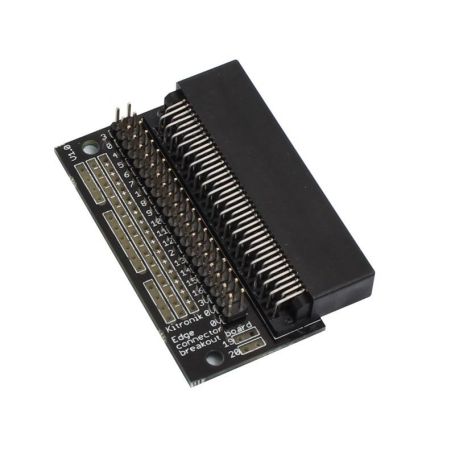
The Connector Breakout Board for the micro:bit gives access to all of the important pins on the bottom edge of the board. 21 pins are available on the connector; providing additional I/O lines, direct access to buttons A and B, the LED matrix outputs and the I2C bus. See the datasheet in the tutorial section.
The pins are broken out to a row of pin headers. It provides an easy way for connecting circuits by using jumper wires. The SCL and SDA pins available on separate pads (on the edge of the connector board) for an easy identification. The board includes power rails for 3V, 0V and a free usage rows that can be soldered to. This allows the easy connection of switches, sensors and any pull-up or pull-down resistors etc. as required.
As example of connector usage you can have a look to the following links:
- The breakout board is used in Collision Detection Buggy that makes use of the extra I/O available.
- The Connector Breakout Board is also included in the Inventor's Kit for the BBC micro:bit. It is used to facilitate the wiring.
To use the breakout board the Micro:bit should be inserted firmly into the connector as shown in the product's picture.
Requires a Micro:bit to be used.
Features
- Features a dedicated pin strip for quick and easy prototyping.
- Breaks out 21 pins from the edge of the BBC micro:bit.
- Dedicated power rail for 3V and 0V.
- Labelled pins and clear straightforward documentation.
Dimensions:
- Length: 60mm.
- Width: 40mm.
- Height: 11.8mm.
Tutorials
- Trying out one of the experiments detailed in the Inventors kit for BBC micro:bit.
- Connecteur du Micro:bit (Pdf, MCHobby, Français)
- Micro:bit connector's datasheet (Kitronik)
- Accessing additional pins and functionality on the BBC micro:bit to follow the numerous tutorials available on Internet.
")