


Motor board for Romi Robot
Motor controller for Romi robot
- Motor driver: DRV8838 (2.5 to 10.8V, 1.8A per channel)
- Power distribution
- STEP-DOWN regulator (2.5 @ 5V, 3.3V)

Payments are secured by LyraCollect, a French payment collection company.

It is possible to delivered to your home, to a pick-up point or picked up by appointment at MCHobby

We prepare, pack and ship your orders with great respect and care.
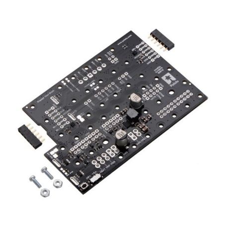
A motor control board for the Romi platform
This motor control and power distribution board is designed specifically for the Romi robotic platform (from Pololu). This board offers a comfortable solution to control the Romi's motors and power the rest of your robot's electronics.
The board is equipped with:
- two DRV8838 motor controllers, a driver for each of the motors present on the chassis.
- a powerful Step-Down voltage regulator (chopper). The regulator is capable of supplying 2.5A at 5V or at 3.3V.
The board provides places to insert the battery contacts available on the Romi chassis. It also includes a power cutoff circuit and power distribution rails.
The power section of the board offers the following features: reverse power protection, several power options (5V/3.3V), a power cut button, easy access to the different power buses.
The small push button present on the board cuts the power of the board (once to turn off, another time to turn on). Contact points allow you to weld a push button that can be deported elsewhere on your robot (the buttons are mounted in parallel).
Alternative connections allow soldering two separate buttons, a button for power-on and another button for power-off. A final input of the power supply circuit allows the microcontroller to cut the power of the robot (therefore to turn off by itself).
Finally, a last option allows you to reconfigure the power supply circuit to deactivate the push button to control the power supply with the small on/off switch already welded on the board.
The control pins of the board and the power buses are all available on connectors with impaction of 2.54mm where it's possible to weld standard male or female connectors.
The power buses are also accessible on the edge of the board and the hole spacing allows soldering to 3.5mm impaction terminal blocks (it's possible to combine a 2-position terminal block and a 3-position terminal block to create the 5-position terminal block).
The board is delivered with the screws allowing to fix the board on the Romi chassis (2x 1/4″ screws #2-56 and 2x nut #2-56). A low profile female connector is included to connect the motors to the board.
Motor Controller
The motor board is equipped with two Texas Instruments DRV8838 controllers allowing the Romi chassis to be moved via its two motors. We recommend that you read the DRV8838 datasheet carefully for more information on the driver.
By default, the motor supply voltage (VM) is supplied by the -interruptible- power supply of the board, VSW. The motor controller logic voltage (VCCMD) is supplied by the board's voltage regulator, VREG (5V by default).
If you wish to customize these voltages, it's possible to cut the jumper VM = VSW and VCCMD = VREG and connect the desired power supplies to VM and VCCMD.
The DRV8838 offers a control interface based on two PHASE/ENABLE pins which, on this board, is accessible via the DIR and PWM pins for each of the motors
- The DIR pin determines the direction of the motor (down to move forward, up to move back).
- The PWM pin can be powered by a PWM signal to control the speed of the motor.
The DIR and PWM inputs are automatically recalled to ground by the internal pull-up resistors (~ 100 kΩ) present on the board. When the PWM pin is at low level, the two motor outputs are connected to ground, which corresponds to active braking of the motor.
The two SLEEP pins (labeled SLP) of the controllers are connected together and can be placed to the ground by the microcontroller to deactivate the motor controllers (energy saving mode), which will deactivate the motors (freewheel). The SLEEP pins are kept at the hait level using a 10 kΩ pull-up resistor. By default the motor drivers are therefore active.
The SLEEP pin can remain disconnected in most cases; if you want to control the SLEEP pin then you can cut the jumper L = R. The two SLEEP pins should not be controlled separately without cutting this jumper.
The simplified truth table below indicates the different modes of operation of the controller:
| DIR | PWM | /SLEEP | Motor+ | Motor- | Operating mode |
| 0 | PWM | 1 | PWM | Low | Forward at speed %PWM |
| 1 | PWM | 1 | Low | PWM | Rear at speed %PWM |
| X | 0 | 1 | Low | Low | Braking (outputs to ground) |
| X | X | X | Z | Z | Freewheel (floating outputs) |
Encoder connection
The board allows the use of motors with encoders. It's possible to connect these encoders to the board to facilitate the various connections necessary with the project.
This point is discussed in detail in the manufacturer's product sheet (in English).
Power button
The push button present on the board can be used to activate/deactivate the power supply of the board. Press once to activate, press a second time to deactivate. A second button can be connected to the BTNA and BTNB pins. Several push buttons can be connected in parallel to control the power from several places. The supply circuit performs a button deworming (several ms) to avoid successive activation/deactivation.
For the board to work properly it's necessary to leave the slide switch on the "OFF" position (placing the slide button on "ON" will activate the power supply circuit of the board but this must be returned to OFF position before being able to deactivate the power supply by pressing the on/off button).
It's possible to modify this operating mode by cutting the jumper "Btn Jmp", which transfers control of the supply circuit to the "ON/OFF" slide switch. an external slide (or bascule) switch can be connected to the GATE pin.
Advanced control options are available through the following pins:
| Pin | Description |
| BTNA | Connected to "BTNB" via a push button to control the push-on/push-off operation. Connected to ground via a momentary button for "on-only" operation. |
| BTNB | Connected to "BTNA" via a push button to control the push-on/push-off operation. |
| ON | A high level pulse (> 1 V) on this pin activates the power control circuit. This pin operates only if the operating mode of the power supply is configured to "push button" mode (eg the button jumper having been cut). |
| OFF | A high level pulse (> 1 V) on this pin enables the power supply control circuit to be deactivated (eg allows the robot to cut its own power supply). This pin only works on the power supply and is configured in "push button" mode. |
| CTRL | With a power supply configured in "push button" mode, this pin directly impacts the state of the power supply circuit. A high level pulse (> 1 V) on this pin will activate the power supply of the board; a pulse at the low level will deactivate the power supply of the board (ex: by forcing the pin at the low level or by connecting a button to ground and pressing it). Leaving this floating pin (disconnected) will not attempt to change the state of the power supply. Note that this pin should never be forced at high level while the "OFF" pin is forced at high level. |
| GATE | When the "Push Button" mode is deactivated (the "button" jumper cut), this pin controls the state of the power supply circuit: forcing it at low level will activate the supply circuit, while left floating will deactivate the supply . Connected to a slide switch (or bascule switch) connected to ground, it is possible to activate/deactivate the power supply of the board. Pololu recommends only forcing the GATE pin to ground or leaving the floating pin; this pin should never be forced at high level while the switch is placed in the "Stop" position. |
Distribution circuit
The board uses different power points:
- VBAT is connected to the battery contact marked BAT1 + and offers a direct connection to the battery supply. By default, VBAT corresponds to the positive side of the 6 AA batteries under the chassis (in series). The battery configuration can be changed using the jumper (see below).
- VRP offers access to power after the protection diode against reverse polarisation.
- VSW is the supply voltage after the protection diode and the power cut circuit (SW stands for Switch). By default, this power rail is used to supply the necessary power to the motors (VM) via the motor controller.
- VREG is the output of the voltage regulator (step-down) present on the board (see section "Voltage regulator" below). By default, this regulator produces a voltage of 5V and the logic voltage of motor controllers (VCCMD) as well as the supply voltage of the encoders (VCCENC and VPU).
- BAT2+ offers access to the positive pole of two AA batteries in series. This can be useful if you want to use two different voltage sources.
Voltage Regulator
A MP4423H voltage regulator (DC-DC chopper) allowing the battery voltage (VSW) to be lowered to the VREG output voltage. By default, the output voltage is 5V but can be changed to 3.3V by cutting the track of the VREG Select jumper.
This regulator is capable of delivering an output current up to 2A, current available on the VREG power rail.
Battery power configuration
The motor control and power distribution board is configured by default to provide VBAT power from the 6 AA batteries in the chassis connected in series (nominal voltage of approximately 7.2V with rechargeable batteries or 9V with Alkaline batteries).
It is however possible to modify the jumper labeled Bat Jmp to reconfigure the connections in order to offer two independent power supplies:
- BAT1 with 4 batteries in series (nominal voltage of 4.8V rechargeable or 6V alkaline).
- BAT2 with 2 batteries in series (nominal voltage of 2.4 V rechargeable or 3 V alkaline).
Cutting the connection between BAT1− and BAT2 + separates the two sets of batteries, and using solder to bridge BAT1− and GND makes it possible to create a common ground between the two power supplies.
If you are interested in this point, we recommend reading the "battery supply configuration" section on the supplier product sheet. It contains some important details to know.
Tutorials
Tutorials and additional information are available on the product sheet of Pololu, the manufacturer of this product.
- Motor Driver and Power distribution Board for Romi chassis (Pololu, English)
- DRV8838 datasheet (Texas Instrument, English)