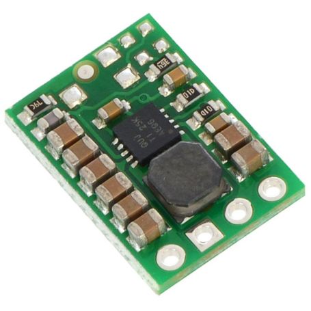


3.3V regulator, 500-1000mA, Step Up/Down, S7V8F3
S7V8F3 DC-DC Regulator
- Input: 2.7 to 11.8V
- Output: 3.3V @ 500 - 1000mA
- Step-Up/Down
- Non rechargeable or NiMH battery
- Shutdown

Payments are secured by LyraCollect, a French payment collection company.

It is possible to delivered to your home, to a pick-up point or picked up by appointment at MCHobby

We prepare, pack and ship your orders with great respect and care.
Generate 3.3V output voltage with an efficient DC-DC regulator
The S7V8F3 is a step-up/step-down switching power supply regulator provides an output voltage of 3.3 V. As it is a step-up/step-down regulator, it can work with a voltage higher or lower than the output voltage.
This regulator accepts an input voltage range from 2.7 V to 11.8 V.
This regulator also has a fixed turn-off voltage of 2.7V (base voltage turn-off) used to prevent the battery from being over-discharged. It is more suited for NiMH or usual alike batteries since LiPo have a stricte minimum of 3V.
This compact 11.5mm x 16.50mm module is capable of supplying a typical current of 500 to 1A depending on the conditions.
Step-up, Step-Down... What about it?
These are characteristics of switching regulators. A Step-Up regulator is able to increase the voltage to reach the desired voltage. A Step-Down regulator will be able to handle a higher voltage input to reach the desired voltage.
A Step-up/Step-down regulator is able to reach the desired voltage from a lower or higher supply voltage. The latter model is useful if you need to keep a project running for as long as possible with a power source whose voltage drops over time (for example: battery).
Description (following)
The S7V8F3 series of regulators are high efficiency choppers using the buck-boost typology to convert a lower (or higher) voltage to the output voltage. The S7V8F3 family accepts an input voltage of 2.7 V to 11.8 V and offers a typical efficiency greater than 90% for a typical current of up to 1.0 A (if the input voltage is greater than the output voltage). Otherwise, in step-up mode, the regulator can only supply 500mA.
The regulator's high efficiency means they run cooler than linear regulators.
The input voltage flexibility makes it a perfect tool for battery-operated projects where, during discharge, the voltage drops steadily and eventually falls below the regulator's output voltage. Being able to produce the desired output voltage even with a very low input voltage is really ideal for embedded projects. This allows the use of smaller batteries for longer life.
This regulator has a shutdown input (SHDN) which deactivates the regulator and reduces its consumption to around 0.1mA
Characteristics
- Input voltage: 2.7 V to 11.8 V
- Output Voltage: Fixed 3.3 V with +5/-3% accuracy.
- Output Current: 1.0 A (typical maximum continuous output current)
(when input voltage drops under 3.3V then the typical current falls aroung 500mA) - Shutdown: the SHDN tied to the GROUND will disable the power regulateor (and reduce the current to 0.1mA)
- Protection: Integrated over-temperature and short-circuit protection
- Small size: 11.5 × 16.5 × 4.3 mm
Use the regulator
During the operation of the regulator, the temperature may become high enough to burn you. Be careful when handling this product and those connected to it.
Connection
This regulator have 4 main connections, each one labelled on the board:
- VIN: input voltage.
- GND: the ground.
- VOUT: Output voltage.
- SHDN: disable the regulator when tied to the ground.
The output voltage, VOUT, fixed at 3.3 V .
The input voltage, VIN, must be in the range 2.7 V to 11.8 V. Lower inputs will shut-down / cutt-off the regulator. Voltage higher than 11.8V will destroy the regulator (so avoid noise on the input and the desctructive LC spikes).
When the SHDN pin falls below 0.4 V then the regulator enters low-power sleep state.
Efficiency and output current
The efficiency of a voltage regulator, is defined as: Power out / Power in.
This ratio measures performance, an important point when battery life (or the heat generated by the regulator) is a critical point of the project. In fact, the poorer the efficiency, the more power the regulator dissipates (generally in the form of heat).
The graph below shows the efficiency (between 85 and 95%) in many scenarios.
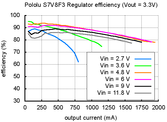
You can find more details on the regulator from the manufacturer web page.
The maximum output current depends on the input voltage but also on other factors such as ambient temperature, output current, presence of heatsinks and ventilation.
Depending on the input or output voltage, this regulator is capable of delivering current up to 2A (temporarily) but the regulator will quickly and actively heat up the thermal protection (which will turn off the regulator).
Generally, above a supply voltage of 3.6V, the regulator guarantees an output current of 1A. When the voltage drops below 3.6V then the current that can be produced is quickly limited to 500mA.
The graph below shows the maximum current obtainable as a function of input voltage. This corresponds to the maximum current (peak) that can be obtained for a few seconds before the overheating protection is activated.
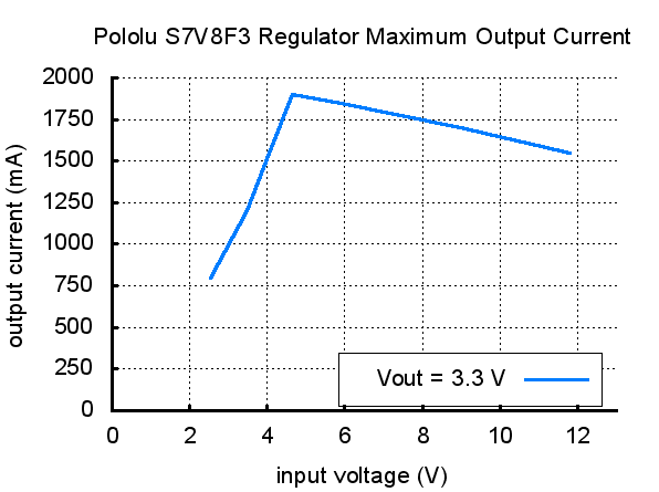
We do advise to not exceed the 1 A (1000mA) output current.
Overvoltage spikes caused by LC circuits
When you connect the voltage to an electronic circuit, the initial current call can cause a overvoltage spike that can be much higher than the input voltage. The regulator may be destroyed if these overvoltage spikes exceed the maximum permitted voltage. IF you connect a power supply of approximately 9V (and more), or use branch wires exceeding 5cm, or use a power supply with a high inductance THEN we recommend to weld a capacity of 33µF or large electrolytic capacity near the regulator between VIN and GND. The capacity must be able to withstand a voltage of at least 16V.
You will find more information about LC over-voltage in the pololu application notes, see "Understanding Destructive LC Voltage Spikes".