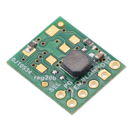


3.3V / 5V, 1.5A regulator, Step Up/Down, S9V11F3S5C3
Swtich regulator S9V11F3S5C3
- 3.3V (default) / 5V (selectable)
- 1.5A
- Step-Up/Down

Payments are secured by LyraCollect, a French payment collection company.

It is possible to delivered to your home, to a pick-up point or picked up by appointment at MCHobby

We prepare, pack and ship your orders with great respect and care.
Generate 3.3V (or 5V) output voltage with an efficient DC-DC regulator
The S9V11F3S5C3 is a step-up/step-down switching regulator (DC/DC regulator) producing 3.3 V (by default) or 5 V (selectable) output voltage. As it is a step-up/step-down regulator, it can work with an higher or lower input voltage to produce the desired output voltage.
This regulator accepts an input range from 3 V to 16 V.
The regulator also has fixed 3 V low-voltage cutoff with hysteresis that can be used to prevent battery over-discharge.
The compact 12.7mm x 15.24mm module can supply a typical output current of up to 1.5 A when the input voltage is close to the output voltage.
Step-up, Step-Down... What about it?
These are characteristics of switching regulators. A Step-Up regulator is able to increase the voltage to reach the desired voltage. A Step-Down regulator will be able to handle a higher voltage input to reach the desired voltage.
A Step-up/Step-down regulator is able to reach the desired voltage from a lower or higher supply voltage. The latter model is useful if you need to keep a project running for as long as possible with a power source whose voltage drops over time (for example: battery).
Description (following)
The S9V11x series are efficient switching regulators using a buck-boost topology to convert a lower or higher voltage to the output voltage. The S9V11X familly accept input voltage from 2 V to 16 V and offers a typical efficiency higher than 85% (with typical output current up to 1.5 A).
The flexibility input voltage made it well suited for battery-powered projects where the battery voltage begins above the regulated voltage and drops under the output voltage (as the battery discharges). Being able to produce the desired output voltage even with very low input voltage would be really great for embedded project allowing to use smaller batteries with extended time life.
The S9V11x series contains several regulator with different output voltage, from fixed voltages (with selectable alternatives adjustable between 2.5 V and 9 V, voltage selected with turn potentiometer). Several regulator also have cutoff low-voltage (selectable, from 2 V to 16 V) that prevent the battery over-discharging. This is great for battery like LiPo or LiIon that have chimistry becoming unstable when over-discharging them The table here below resume the various regulator and their key features:
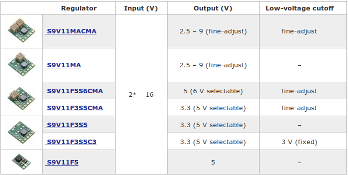
* The regulator has a minimum start-up voltage of 3 V, but it can operate down to 2 V after startup. It is disabled when the input voltage is below the low-voltage cutoff.
Characteristics
- Input voltage: 3 V to 16 V
- Output Voltage: Fixed 3.3 V with +5/-3% accuracy.
Can be changed to 5 V using the SEL pin - Output Current: 1.5 A (typical maximum continuous output current)
(when input voltage is close to the output; the Typical efficiency and output current section below shows how the achievable continuous output current depends on the input and output voltages) - Cut-off: Fixed 3 V low-voltage cutoff with hysteresis protects batteries from over-discharging (quiescent current is approximately 10 µA per volt on VIN when regulator is disabled)
- Power-good indicator: indicates when the regulator has reached and is maintaining its target output voltage
- Power-saving: feature maintains high efficiency at low currents (quiescent current is less than 1 mA while enabled)
- Protection: Integrated over-temperature and short-circuit protection
- Small size: 12.7 × 15.3 × 4.3 mm
Use the regulator
During the operation of the regulator, the temperature may become high enough to burn you. Be careful when handling this product and those connected to it.
Connection
This regulator have 5 main connections and one optional connection (named SEL), each one labelled on the board:
- VIN: input voltage.
- GND: the ground.
- VOUT: Output voltage.
- EN: Enable input (activate the regulator)
- PG: Power good (output signal)
- SEL: select alternate voltage (5V)
The output voltage, VOUT, fixed at 3.3 V (by default) but can be set to 5 V with the SEL pin (output voltage selection pin).
The input voltage, VIN, must be in the range 3 V to 16 V. Lower inputs will shut-down / cutt-off the regulator. Voltage higher than 16V will destroy the regulator (so avoid noise on the input and the desctructive LC spikes).
When the EN pin falls below 0.7 V then the regulator enters low-power sleep state. The regulator exists sleep mode EN is over 0.8 V.
This regulator version have EN pin is tied to VIN through a voltage divider (154 kΩ to VIN and 47 kΩ to ground). This sets the sets the low-voltage cutoff threshold to 3 V. When input voltage falls under 3V (the threshold) then the regulator will stay disabled until the input rises above 3.4 V. When the input voltage is above 3.4V then the EN voltage rise past its 0.8V hysteresis threshold.
The quiescent current draw in this sleep mode is dominated by the current in the voltage divider (about 10 µA per volt on VIN, so ~30 µA with 3 V in).
PG is the "power good" indicator, an open-drain output that goes low when the regulator’s output falls below around 90% of the nominal voltage. The PG also goes low when the EN (enable pin) is held low.
Note that PG is maintained low until the output reach 95% of nominal voltage (when powered up or re-ENabled). External pull-up resisitor is required on PG pin for the high level.
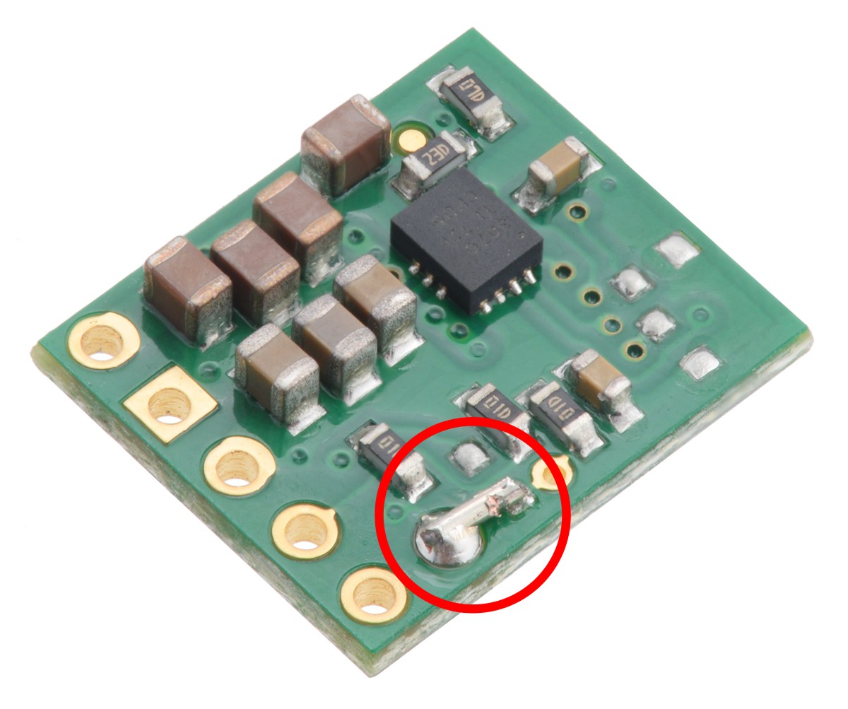
The select input, SEL is use to change to output voltage to 5V (when driven over 1.1 V up to 16 V). Driving the pin low (or disconnected) then the regulator switch to 3.3 V output.
Solder a wire between SEL and VIN to permanently set the output to 5 V (see the picture below):
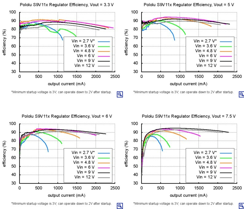
Efficiency and output current
The efficiency of a voltage regulator, is defined as: Power out / Power in.
This ratio measure the performance, especially when battery life or heat are concerns. The graph below show the regulator efficiency (between 85 & 95%) in many situation. A power-saving feature maintains these high efficiencies even when the regulator current is very low.
More details about efficiency on the Pololu website.
The maximum output current depends on the input voltage but also of other factors (ambient temperature, air flow, heat sinking). The graph below shows maximum output currents that can be sourced continuously without additional heat sinking.
Depending on the input and output voltage, these regulators can deliver over 2 A (temporary), though they will typically quickly overheat under such conditions (and activate the thermal shutdown).
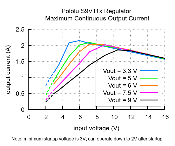
The startup current is limited to ~700 mA when input voltages > output voltage and additional current of this is only available after the output has finished stabilizing.
For input voltages below the output voltage, the available start up current decreases linearly with the input voltage to approximately 0.3 A with an input of 3 V.
Large capacitive loads will charge up gradually and will not cause any problems (even with the current limit active), so while they may increase the time it takes an S9V11x family regulator to start up, the regulator should still eventually stabilize. A purely resistive load, however, could prevent the regulator from ever reaching the desired output voltage. For example, if the output of the regulator is 5V and you put a 5 Ω resistor between VOUT and GND and then apply power to the regulator, the output voltage will never rise past 3.5 V, the voltage at which the current draw reaches the 700 mA limit.
This family of regulators is intended for applications like robotics, where any large loads are controllable and can be applied only after the regulator has finished starting up.
Overvoltage spikes caused by LC circuits
When you connect the voltage to an electronic circuit, the initial current call can cause a overvoltage spike that can be much higher than the input voltage. The regulator may be destroyed if these overvoltage spikes exceed the maximum permitted voltage. IF you connect a power supply of approximately 9V (and more), or use branch wires exceeding 5cm, or use a power supply with a high inductance THEN we recommend to weld a capacity of 33µF or large electrolytic capacity near the regulator between VIN and GND. The capacity must be able to withstand a voltage of at least 16V.
You will find more information about LC over-voltage in the pololu application notes, see "Understanding Destructive LC Voltage Spikes".