


5V 5A regulator, Step-up, U3V50F5
U3V50F5 DC-DC converter, 5V 5A max, Step-Up
- Output voltage: 5V
- Input voltage: from 2.9V
- Input current: 5A max

Payments are secured by LyraCollect, a French payment collection company.

It is possible to delivered to your home, to a pick-up point or picked up by appointment at MCHobby

We prepare, pack and ship your orders with great respect and care.
Power up your 5V project with efficient with this step-up converter
These boost (step-up) voltage regulators generate higher output voltages (5v) from a lower input voltages (as low as 2.9 V). They are switching regulators (also called DC-to-DC converters) and have a typical efficiency between 80% to 95%. The output current available depend on the input voltage, output voltage and the efficiency (see Efficiency vs Output Current chart) but the input current is limited to 5 Amp max.
The regulator has built-in protection covering reverse-voltage, over-current, thermal shutdown (activated at 165°C) and under-voltage lockout which turn off the regulator when the input voltage goes below 2.5 V (typical).
In no-load operation, the regulator has a quiescent current between 1 mA and 5 mA for most combinations of input and output voltages.
The ENABLE pin can be used to put the board in a low-power state that reduces the quiescent current to approximately 20 µA per volt on VIN.
Features
- Input voltage: 2.9 V to VOUT
- Output voltage: 5 V with 4% accuracy
- 5 A switch allows for input currents up to 5 A
- Integrated reverse-voltage protection, over-current protection, over-temperature shutoff, and under-voltage lockout
- Typical efficiency of 80% to 95%
Depending on input voltage, output voltage, and load. - Size: 48 × 15 × 10.5 mm
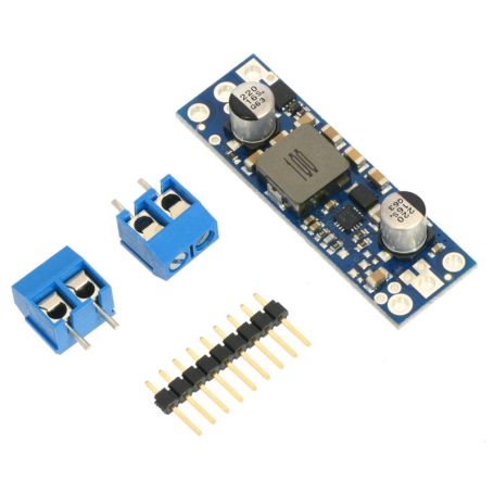
- Mounting holes: 2x M2 screws
- Smaller holes for 2.54mm header pins. There are larger holes for terminal blocks.
Wiring regulator
The regulator has four connections: input voltage (VIN), ground (GND), and output voltage (VOUT), and ENABLE.
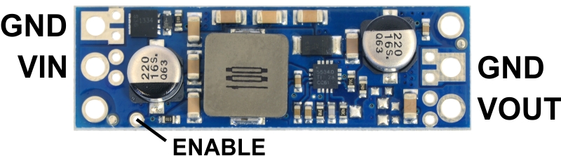
The regulator is enabled by default: a 100 kΩ pull-up resistor on the board connects the ENABLE pin to reverse-protected VIN.
The ENABLE pin can be driven low (under 0.7 V) to put the board into a low-power state.
The quiescent current draw in this sleep mode is dominated by the current in the pull-up resistor from ENABLE to VIN and by the reverse-voltage protection circuit, which will draw between 10 µA and 20 µA per volt on VIN when ENABLE is held low. If you do not need this feature, you should leave the ENABLE pin disconnected. Note that like most boost regulators, the input power will pass through to the output when the board is disabled, so the ENABLE pin cannot be used to turn off power to the load.
Efficiency and output current
The voltage regulator efficiency is defined with the following formula:
Efficiency = Power out / Power in
The efficiency is an important measure which evaluate the performance of the regulator.
When the efficiency decrease, the regulator does have a more important power lost. This power lost is usually transformed in heat. So higher efficiency means less heat (better when temperature is a concerns). Better efficiency also means better battery life.
As shown in the graphs below, these switching regulators have an efficiency of 80% to 95% for most combinations of input voltage, output voltage and load.
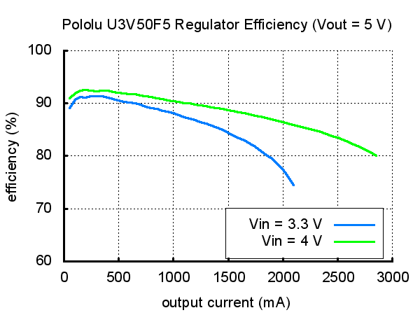
The output current max is almost proportional to the input_voltage/output_voltage.
If the input current exceeds the 5 A switch current limit then the output voltage will start to to drop.
The maximum output current can also depend from other factors like the ambient temperature, the air flow and heat sinking.