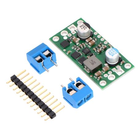
5V 9A regulator, step down, D24v90F5
D27V90F5 Switching DC-DC regulator, 5V 9A, Step-Down
- Output voltage: 5V (and possibility to configure lower)
- Input voltage: 38V max
- Output current: ~9 A max
Payments are secured by LyraCollect, a French payment collection company.
It is possible to delivered to your home, to a pick-up point or picked up by appointment at MCHobby
We prepare, pack and ship your orders with great respect and care.
A DC-DC 5V 9 amps regulator for high-power applications
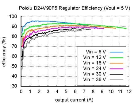
This is a high-current step-down regulators (also named "buck") that generates 5 V output from input voltages up to 38 V. It use a switching regulators (also called DC-to-DC converters) and offers a typical efficiency of 80% to 95%.
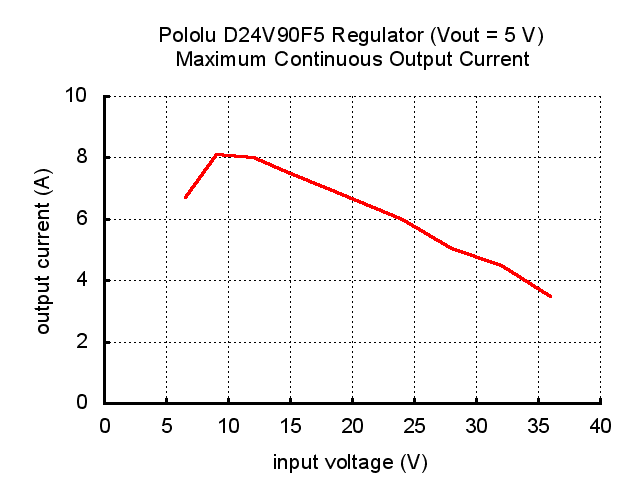
The max output current depend on the input voltage and efficiency (see the Typical Efficiency and Output Current section below). The output current can be as high as 9 A.
The ENABLE pin can be used to put the board in a low-power state that reduces the quiescent current to approximately 10 µA to 20 µA per volt on VIN.
The power good pin (PG) can be used to monitor the state of the main power. The regulator use this pin to signal when it cannot maintain the output voltage.
The output voltage can also be lowered by placing an external resistor between VOUT and FB.
This regulator has built-in reverse-voltage protection, thermal shutdown (activated at 160°C), short-circuit protection, and under-voltage lockout (the regulator to turn off when input voltage < 4.2 V).
The extra feature "soft-start" reduces inrush current at startup.
Features
- Input voltage: 5 to 38 V
- Fixed 5 V output (4% accuracy).
This can be lowered by adding an external resistor between FB and VOUT - Typical maximum continuous output current between 4 A and 8 A
- Integrated protection: reverse-voltage, over-current, over-temperature, under-voltage lockout
- soft-start
- Typical efficiency of 80% to 95% (depends on input voltage and load).
The switching frequency automatically changes at light loads to maintain high efficiencies - Quiescent current: 800 μA typical no-load.
Can be reduced to 10 µA to 20 µA per volt on VIN by disabling the board - Power good output (PG) indicates when the regulator cannot maintain its set output voltage
- size: 40.6 × 20.3 × 7.6 mm
- 4x M2 screws
- Smal holes for 2.54 header pins
- Larger holes for terminal blocks offer several options for connecting to the board
Wiring
This buck regulator has six connections: VIN, GND (ground), VOUT (output voltage), FB (feedback), ENABLE and PG (power good).
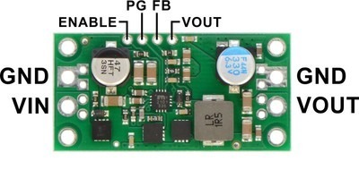
- VIN : input voltage. Powers the regulator and can be supplied with voltages up to 38V.
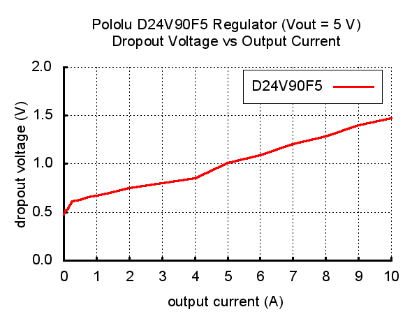
The effective lower limit of VIN is VOUT plus the regulator’s dropout voltage, which varies approximately linearly with the load from around 500 mV to 1.5 V (see below for a graph of the dropout voltage as a function of the load). - VOUT : output voltage. Is set to 5V by default.
The output voltage can optionally be lowered by adding a resistor between the FB pin and VOUT as detailed in the Decreasing the output voltage section below. - ENABLE pin : The regulator is enabled by default with a 100 kΩ pull-up resistor on the board connects the to reverse-protected VIN.
The ENABLE pin can be driven low (under 0.6 V) to put the board into a low-power state. The quiescent current draw in this sleep mode is dominated by the current in the pull-up resistor from ENABLE to VIN and by the reverse-voltage protection circuit, which will draw between 10 µA and 20 µA per volt on VIN when ENABLE is held low. If you do not need this feature, you should leave the ENABLE pin disconnected. - PG pin : "power good" indicator. This pin is an open-drain output that goes low when the regulator’s output voltage falls below 90% of what it is set to (i.e. 4.5 V with the default 5 V output setting). An external pull-up resistor is required to use this pin.
Decreasing the output voltage
The set voltage can optionally be decreased by adding an external resistor between the FB and the neighboring VOUT pin. The equations below show how the output voltage relates to the value of an external resistor, R:
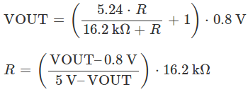
In this example, to get 3.3v as output voltage, you should place a 23.7 kΩ resistor between FB and VOUT.
The minimum VOUT for this regulator is 0.8 V.
Note: the small VOUT pin next to FB is not intended to source much current; its is a convenient spot for connecting a voltage-adjustment resistor.
Efficiency and output current
The voltage regulator efficiency is defined as (Power out)/(Power in). It is an important measure of the performance, especially when battery life or heat are concerns.
The graph below whos the switching regulators efficiency. The efficiency of 80% to 95% for most combinations of input voltage, and load. A lower efficiency imply a high power dissipation (then dissipate more heat).
The maximum output current of the board depends of several factors:
- the ambient temperature,
- air flow,
- heat sinking
- input and output voltage.
The graph below shows the maximum continuous output current this regulator can deliver with no external heat sinking or added air flow.
During normal operation, this product can get hot enough to burn you. Take care when handling this product or other components connected to it.
Typical dropoup voltage
The dropout voltage of a step-down regulator is the minimum amount by which the input voltage must exceed the regulator’s target output voltage in order to ensure the target output can be achieved.
Ex: if a 5 V regulator has a 1 V dropout voltage, the input must be at least 6 V to ensure the output is the full 5 V.
The following graph shows the dropout voltage for the regulator as a function of the output current:
Switching frequency and behavior under light loads
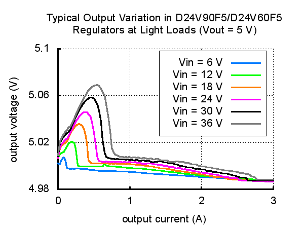
The regulator operates at a switching frequency of 470 kHz. The frequency can drops when encountering a light load in order to improve efficiency.
A lower switching frequency could make harder to filter out noise on the output (noise caused by switching). Frequency dropping also causes small variations in the output voltage like shown in the graph below.
