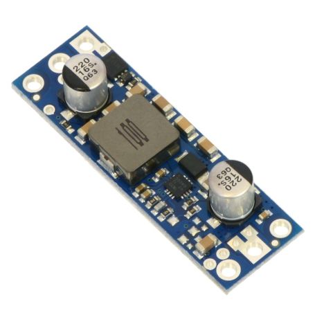


Regul. 6V 1500-3000mA, Step Up, U3V50F6
Pololu 6V Step-Up Voltage Regulator U3V50F6

Payments are secured by LyraCollect, a French payment collection company.

It is possible to delivered to your home, to a pick-up point or picked up by appointment at MCHobby

We prepare, pack and ship your orders with great respect and care.
Description
This powerful boost regulator efficiently generates an output voltage of 6 V from an input voltage as low as 2.9 V while allowing an input current as high as 5 A.
The avaibable current at the output depend on the input voltage. You can see on the Efficiency graph that 3.3V input allows you to obtain 1.5A and 5V input allow a current up to 3 Amp.
These boost (step-up) voltage regulators generate higher output voltages from input voltages as low as 2.9 V. They are switching regulators (also called switched-mode power supplies (SMPS) or DC-to-DC converters) and have a typical efficiency between 80% to 95%. The available output current is a function of the input voltage, output voltage, and efficiency (see the Typical Efficiency and Output Current section below), but the input current can typically be as high as 5 A
Step-up, Step-Down... what's that?
Step-Up is a est un term used when we "increase" the voltage where as Step-Down is used when we "descrease" the voltage.
This is a feature of DC-DC regulator (switching regulator). A Step-Up regulator is able to increase the input voltage to reach est wanted voltage at the output. A step-down regulator with decrease the input voltage to reach the wanted output voltage.
The Step-up/Step-Down regulator is able to reach the wanted voltage either from a higher input voltage, either from a lower input voltage. This last combination is quite useful if you need to keep your project powered until the last snip of energy in the battery. In the real world, the battery continuously decrease while the battery is decharging.
Description (part 2)
This flexibilty regarding the input voltage is very convenient for projects using batteries where the voltage usually start over 5 volts then decrease continuously when the battery is discharging. Without this constraint of maintaining a absolute minimum voltage all along the live cycle of the batteries for the project, you can now rely on the DC-DC regulator.
The key advantage of using a DC-DC regulator you can now choose a suited battery pack or Lipo form factor for your project.
The no-load quiescent current depends on the difference between the input and the output voltage. When the two are close, the quiescent current can be less then a milliamp (e.g. 0.6 mA with 5 V in and 6 V out); when the two are far apart, it might be in the tens of milliamps (e.g. 24 mA with 3 V in and 24 V out). The ENABLE pin can be used to put the board in a low-power state that reduces the quiescent current to approximately 20 µA per volt on VIN.
This regulator has built-in reverse-voltage protection, over-current protection, thermal shutdown (which typically activates at 165°C), and an under-voltage lockout that causes the regulator to turn off when the input voltage is below 2.5 V (typical).
Features
- Input voltage: 2.9 V to VOUT
- Output: fixed to 5V (4% accuracy)
- 5A switch allows for input currents up to 5A
- Output current: depend on the input voltage, please refer the graph (in the product sheet)
- Integrated reverse-voltage protection, over-current protection, over-temperature shutoff, and under-voltage lockout
- Typical efficiency of 80% to 95%, depending on input voltage, output voltage, and load
- Compact size: 48 × 15 × 10.5 mm
- Two mounting holes for M2 screws
- Smaller holes for 0.1″ header pins and larger holes for terminal blocks offer several options for connecting to the board
Using the regulator
During normal operation, this product can get hot enough to burn you. Take care when handling this product or other components connected to it.
Connections
This boost regulator has four connections: input voltage (VIN), ground (GND), and output voltage (VOUT), and ENABLE:
- VIN: input voltage.
- GND: common ground to input and output.
- VOUT: Output voltage.
The input voltage, VIN, must be at least 2.9 V and should not exceed the output voltage, VOUT. (If VIN is higher than VOUT, the higher input voltage will show up on the output, which is potentially dangerous for your connected load and could also damage the regulator.)
The regulator is enabled by default: a 100 kΩ pull-up resistor on the board connects the ENABLE pin to reverse-protected VIN. The ENABLE pin can be driven low (under 0.7 V) to put the board into a low-power state. The quiescent current draw in this sleep mode is dominated by the current in the pull-up resistor from ENABLE to VIN and by the reverse-voltage protection circuit, which will draw between 10 µA and 20 µA per volt on VIN when ENABLE is held low. If you do not need this feature, you should leave the ENABLE pin disconnected. Note that like most boost regulators, the input power will pass through to the output when the board is disabled, so the ENABLE pin cannot be used to turn off power to the load.
Typical efficiency and output current
The efficiency of a voltage regulator, defined as (Power out)/(Power in), is an important measure of its performance, especially when battery life or heat are concerns. As shown in the graphs below, these switching regulators have an efficiency of 80% to 95% for most combinations of input voltage, output voltage, and load.
The maximum achievable output current is approximately proportional to the ratio of the input voltage to the output voltage. If the input current exceeds the 5 A switch current limit, the output voltage will begin to drop. Additionally, the maximum output current can depend on other factors, including the ambient temperature, air flow, and heat sinking.