


prototyping board fro PYBStick
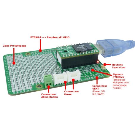
Prototyping board for PYBStick
- Prototyping Area
- Power terminals
- 3x PYBStick breakouts
- 1x Raspberry GPIO (connector)
- 2x Grove (connector)
- 1x UEXT (connector)

Payments are secured by LyraCollect, a French payment collection company.

It is possible to delivered to your home, to a pick-up point or picked up by appointment at MCHobby

We prepare, pack and ship your orders with great respect and care.
The ultimate prototyping board for PYBStick
This board is fitted with a large prototyping area of 296 points as well as duplicates of PYBStick pins over 3 usable row. Il will be easy to make connexion between the prototyping aread and the PYBStick's signals.
Tips & tricks: using female connectors (13 points) on duplicated signals will be handy to make prototyping with breadboard as each pin is also labelled on the PCB. Such 13 pin connector can be made from a 16 pins female connector where you removes 3 rows.
This board is full of connectivity option:
- 2x Grove ports
- 1x power terminal
- 1x Raspberry-Pi's compatible GPIO
- 1x UEXT connexion point
The Grove ports will allow you to plug Grove sensors 3.3V compatible. The both connectors are connected in parallele one the I2C(2) bus (for pins S11 & S13). So you can use the I2C or digital sensors on such connectors. The S11 and S13 pins can produce PWM signals.
Please note that Standard PYBStick are 5V tolerant on almost all pins.
The GPIO connector does respect the Raspberry-Pi connexion standard (on the first 26 pins) so you can plug Raspberry-Pi's HATs on the Proto-Face. Once the 2x20 pins connector soldered, you can plug a HAT onto it and control the HAT from the PYBStick (like a PiFace digital or Hat-Sense).
Warning: the HATs are connected on the back of the PYBStick-Proto-Face board, so you keep full access to the prototyping area and to the PYBStick.
This connecteur can also be used to connect the Proto-Face onto a Raspberry-Pi (with a 2x20 female connector). In this case, the prototyping board ans the PYBStick becomes an extension board for the Raspberry-Pi and the two boards can communicates with each other via the I2C bus (shared on the same GPIOs).
Power connector is protected by a diode. This terminal can be used to power the PYBStick on its VIN pin (18V max, do not go over 12V as rule of thumb and use 5V to avoids any kind of accidents).
The LED will bright when VIN is under power.
PAY ATTENTION to the jumper configuration when powering up the board thought the power terminal when HATs are used on this board.
The jumpers under the board will be used to configure the power distribution to the HAT plugged on the GPIO connector. The solder jumper are located on the back of the board (near of the GPIO's connector).
See the schematics in the product's images for more informations.
- JP1, JP2, JP3 opens: the HAT will not be powered up.
- JP2 soldered: set tge PIN #2 and PIN #4 at the same potential. Usually used when HATs are plugged onto the GPIO connector.
- JP1+JP2 soldered: the GPIO is 5V powered from VBUS (so from the PYBStick's USB)
- JP3+JP2 soldered: the GPIO is powered from VIN (from the power terminal).
Do not use voltage over 5V in such case! - JP1 & JP3 soldered and JP2 open: custom board usage (NON HAT!!!) receiving two distincts voltages: 5V for logic AS WELL as higher voltage on VIN (>5V, <18V)... allowing to create exotic and power greedy extension board.
The JP4 jumper, also available on back of the board, will be used to propagate the /RST signal to the GPIO connector. This will make sense if you are using some custom board -OR- will allow a Pi to reset the MicroControler.
As rule of thumb, we do not recommend to jump JP4 except if you do need it.
Assembly the various items in this kit should take only view minutes. Place the pinHeader onto your PYBStick then place the PYBStick+Headers onto the ProtoFace board. Flip it over then solder the pinHeader pins under the board. Voila!
Video presentation
See this French video showing some of the features of the Proto-Face for the PYBStick.
What's UEXT ?
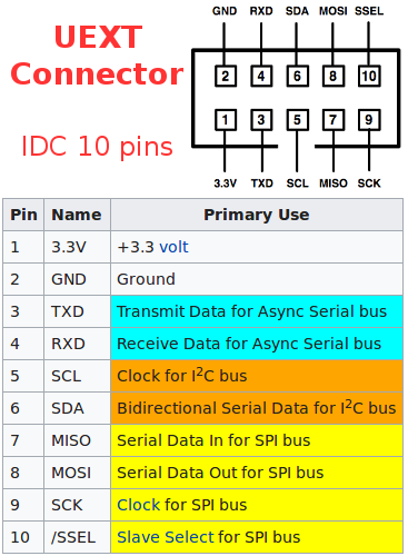
The board does have connection point to solder an UEXT connector available here on the webshop.
UEXT is a connector carrying I2C bus + SPI bus + Serial + 3.3v power. It use a very standard 10 Pin IDC connector. It is quite easy to add sensors and extension board with UEXT connector... just plug it or wire it with IDC ribbon! Great.Our favorite is the carrying of I2C bus allowing to easily add several sensors and expansion board. On the other side, SPI would be welcome for fast data transmission like remote screen. The serial connexion could be made compatible with RS-232, RS-422, RS-485, DMX512, MIDI by using appropriate level-shifting circuitery.
This connector is usually available on almost Olimex's product including nano computers. It is a great way to add extension boards on products like ESP8266 WiFi microcontroler or microcontroler board. UEXT is suited for prototyping, school learning (no need for iron) and industrial solution (Olimex produces Industrial Grade boards).
See our UEXT expansion or all products exposing UEXT connector on the shop, the Olimex's UEXT collection, Wikipedia to learn more about UEXT.
Technical détails
- Button for DFU & Reset duplicated on the board
- 196 points prototyping area
- 2 Grove connectors
- Connection point for UEXT connector (available here on the shop)
- PinHeader to connect the PYBStick
- PYBStick pins duplicated over 3 labelled rows
Great to connect 13 position female connector. - Power terminal
Content
For each order, you will receive the PCB, 2 Grove connector, a power screw terminal, two rows of males connectors (pinHeader) to connect the PYBStick.
Some advice: You also order some useful item for this boardlike PinHeader / 2x20 male connector (for the HATs), an UEXT connector (for UEXT expansion boards).
You can also add some female connectors (16 pins to cut out at the 14th position). Such female header will be great for prototyping with bradboard.

")
 - 2x5 - 90° - 2.54mm")