


Distance sensor over 180 degrées - OPT3101 - Time of Flight IR
Distance and proximity sensor
- Up to 1 meter
- 3 Time-of-Flight channel (infrared)
- Field-of-view: 160 degrees (almost 180°)
- 3.3V to 5V
- I2C interface
- MicroPython ready

Payments are secured by LyraCollect, a French payment collection company.

It is possible to delivered to your home, to a pick-up point or picked up by appointment at MCHobby

We prepare, pack and ship your orders with great respect and care.
Make distance measurement / proximity detection over 160° via I2C with a Time-of-fly sensor based on OPT3101
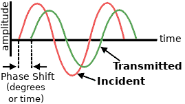
This is a proximity sensor board featuring 3-channels time-of-flight proximity and distance module using the Texas Instrument OPT3101 chip. Usual IR sensor do measure the intensity of the reflected light to evaluate the distance. With the OPT3101 chip, this board send 10 MHz pulsed infrared light (940nm) and mesure the then measures the phase shift of the reflected signal (delay). The phase shift corresponds to the distance of the object. It also measures the amplitude of the signal, which indicates how bright/reflective/close the object is.
This sensor is fitted with 3 IR sensors, 3 channels linked to the OPT3101 chip) each covering about 50° to 60°. This sensor board offers a very wide field of view (FOV) of 160 degrées. In favorable conditions, the sensor can measure objects at distances up to 1 m.
Distance measurements are available through the I2C interface, which is also used to configure the sensor. The board can be used with any I2C capable microcontroler (Arduino & MicroPython drivers are availables).
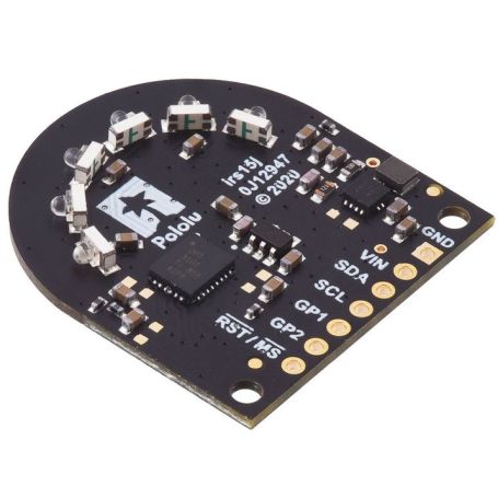
The connexions are made via the 7-pins connector at the rear of the sensor board (great to fix it on a smart vehicule or robot).
The board logic can be powered from 2.5 V up to 5.5 V. The OPT3101 is powered from the On-board 3.3V regulator. Finally, the I2C lines level are shifter to the supplied VIN, so it is a great board for 3.3V & 5V logic microcontroler).
Calibration data included
Each board is fitted with a 256 bytes EEPROM maintaining the factory calibration data. The OPT3101 do automatically loads the calibration data at startup. This calibration defines a distance reading of 100 mm to correspond to an object that is 100 mm from the edge of the board.
Connections
Four connections are necessary to use the OPT3101 board: GND, VIN, SDA, and SCL.
The VIN pin should be connected to a 2.5 V to 5.5 V source. The sensor I2C pins (SCL and SDA) must be connected to the I2C should be connected to an I²C bus operating at the same logic level as VIN.
| Pin | Description |
| GND | The ground connection of the power supply. Your I2C control source (the microcontroler) must also share a common ground with the sensor board. |
| VIN | This is the main 2.5 V to 5.5 V power supply connection. |
| SDA | I2C data line (level shifter, Pulled up to VIN with a 10 KOhms pull-up resistor). |
| SCL | I2C clock line (level shifter, Pulled up to VIN with a 10 KOhms pull-up resistor). |
| GP1 | Configurable 3.3 V I/O pin (Not level-shifted!) |
| GP2 | Configurable 3.3 V I/O pin (Not level-shifted!) |
| /RST, /MS | Input pin used to reset the board or trigger a new sample (Not level-shifted ,3.3V pulled up with a 10 KOhms pull-up resistor). (Both reset & sample trigger can be initiated through I2C.) |
Technical details
- Dimensions: 27.9 mm × 30.5 mm
- Weight: 2.7 gr
- Operating voltage: 2.5 V to 5.5 V
- Sensor channels: 3
(each with an FOV of approximately 50° – 60° for a combined FOV of nearly 180°) - Supply current: 130 mA
(typical average during operation in high-brightness mode with 3.3 V power supply) - Distance range: up to 1 m (depends on the target object)
- Shematic (pdf)
- Supplier product sheet (for more details)
Configuration
The main configuration for the OPT3101 are:
- The channel (0=left, 1=front/middle, 2=right)
- The IR LED brightness (HDR0=low, HDR1=high, or adaptative)
- The sample rate.
These options are set over I2C and they can be changed between samples.
The channel setting determines which pair of IR LEDs will turn on (then determines the sensoring direction).
The low brightness mode is used for nearby objects within ~20 cm. The high brightness mode will be used for longer ranges measurement (note that objects that are too reflective or too close will saturate the sensor, the distance measurement will fails in such situation). The OPT3101 can use one of these brightnesses, or you can make it use an adaptive brightness mode (automatically selecting the High or Low brightness).
The OPT3101 measurements are divided into basic units called a frame or a sample. Each frame has a specific configuration, but you can change the configuration between frames. The OPT3101 can be configured to start frames continuously, or waitng for a signal before starting a frame (which is called monoshot mode, signal send over I2C). When a frame is complete, you can read its results from the OPT3101’s output registers.
Each frame consists of a configurable number of subframes that take 0.25 ms each. The results from each subframe are averaged together. Tip: increasing the number of subframes measurement will reduce the environment noise (but will takes longer to achieves). The number of subframes must be a power of 2 from 1 to 4096.
For more details about how to configure and initialize the OPT3101, please see the Pololu's Arduino library for the OPT3101 or the OPT3101 datasheet.
Tutorial
- Pololu's Arduino library for the OPT3101, which can be used for interfacing this sensor with an Arduino or Arduino-compatible controller. The library and its included examples make it simple to configure the OPT3101 and read the distance data through.
- MCHobby's MicroPython library for OPT3101, which is a portage of the Arduino Library to MicroPython (tested with Raspberry-Pi Pico).