


BASE board for CanSat V2
CANSAT base v2 board with Raspberry Pico
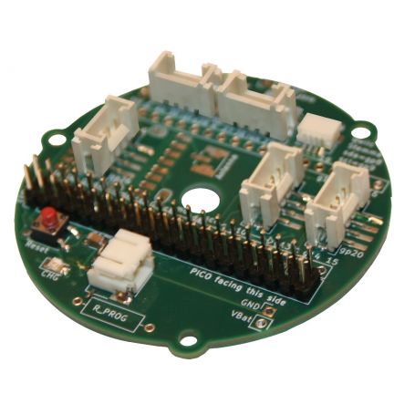
- Fitting for Pico

Payments are secured by LyraCollect, a French payment collection company.

It is possible to delivered to your home, to a pick-up point or picked up by appointment at MCHobby

We prepare, pack and ship your orders with great respect and care.
CanSat V2 development board
This development board is designed to support an MCU card (Microcontroller card like the PICO-CANSAT-MCU) while integrating numerous features and connections intended to facilitate prototyping and electronic discovery.
The base board is designed to accommodate a microcontroller/MCU board from the available range of CANSAT-MCU.
The first version of the Cansat-V2 kit will contains a Raspberry-Pi Pico based MCU (see the Cansat V2 kit with Raspberry-Pi Pico for a complete kit).
The built-in feature are:
- A charger circuit with a connector for Lipo.
- A 3V3 (600mA max) power supply circuit for the project.
- An RFM69HCW radio circuit for data transmission using a wire antenna (µFl footprint for the Ad Hoc connector).
This is the same communication module than RFM69 Radio communication breakout . - A Qwiic/StemmaQt connector for connecting Adafruit, SparkFun, M5Stack sensors.
- Multiple Grove connectors (Serial, I2C, Analog, Digital)
Unlike the previous version, the microcontroller is no longer soldered onto the CANSAT-BASE board. In this second revision, the microcontroller (MCU) is inserted into a vertical 2x20 male connector. See the labels "USB" and "Pico facing this side" to identifying the orientation of the MCU board.
This so-called "MCU board" allows the use of any type of microcontroller/nano-computer compatible with the mechanical constraints of CanSat. The 2.54mm footprint allows advanced users to creates their own MCU card.
The board also fits:
- A Reset button (missing on Raspberry Pi Pico board).
- a PWR ENABLE breakout allowing the CANSAT-BASE voltage regulator and the MCU board to be disabled using a simple switch.
- a complete breakout of the MCU signals, thus allowing additional connections to be made on the GPIOs still available.
Indeed, Grove connectors do not expose all MCU's GPIOs! - Breakout of the Lipo connector allowing the install additional voltage regulator as necessary.
Finally, the board's silkscreen shows numerous annotations, making it easy to identify the connectors and their associated GPIOs.
Any missing information can be easily find on the schematic and inside the tutorial.
Mechanical aspects
This plate has 3 peripheral M2.5 holes allowing mounting with daughter boards to create a cylindrical container.
The big new feature of this revision is the presence of a central hole of 6.4mm diameter.
This hole, available in all the 2nd generation Cansat boards, allows the placement of a central axis or M6 threaded rod, which ensures a solid backbone between the parachute and the bottom of the CanSat.
The outer diameter (excluding attachment points) is now 60.1 mm (compared to 63.9 mm), leaving (66-60.1)/2 = 2.95 mm of thickness for the walls.
The attachment points still fit within the original diameter of 63.9 mm.
This additional space will permit thicker 3D enclosures, even leaving room for wiring.
Qwiic/StemmaQT
The 4-pole JST-SH connector is used by Adafruit Industries and SparkFun electronics for quickly connecting breakouts and sensors using the I2C bus.
The I2C bus is addressable, allowing multiple sensors to be share the same bus.
This connector is now widely used, becoming as popular as the Grove connector (from seeedstudio).
See our connectors document for more information on the PinOut.
Grove
Grove is a SeeedStudio connector that's very popular in Europe. It's also used by M5Stack for its sensors (all 3.3V logic).
This connector is larger than Qwiic/StemmaQt and is therefore easier to handle. The CANSAT-BASE V2 board is equipped with five Grove connectors, providing access to a UART, I2C bus, two analog inputs, and 4 digital inputs/outputs.
These connectors allow you to connect numerous sensors (e.g., a GPS to the UART, a pressure sensor to the I2C bus, etc.). See our connector see our connector tutorial for more information.
It's possible to reassign the function of many pins associated with Grove connectors. This way, the UART and analog inputs can be converted into simple inputs/outputs.
It is strongly recommended to preserve the allocation of the I2C bus, this bus is share over several connectors on the board (including some onboard I2C components).
Grove connectors can also be used with Grove-To-Male cable for rapid breadboard prototyping.
Power the Cansat
The CANSAT-BASE and the MCU board are powered from a Lipo battery.
The CANSAT-BASE have its own 3V3 regulator offering 600mA to your project. The MCU board is responsible for its own voltage regulation.
As soon as the battery is connected, the two boards (CANSAT-BASE & MCU) are powered.
The POWER ENABLE footprint is available on the CANSAT-BASE. Use a switch or connect the pads together with a piece of wire to activates the voltage regulator and save the Lipo battery power.
When the MCU (eg: PICO-CANSAT-MCU) is connected to a computer via USB, the battery starts charging (the orange LED bright).
The MCU board is active when POWER ENABLE is open, otherwise, the MCU board is deactivated but the battery will continue to charge anyway.
Note:
It is recommended to switch-off the the project with POWER ENABLE to make sure the Lipo battery can charge efficiently.
Otherwise, the components og your project will consume some power that can't be stored within the battery.
Content
For each order, you will receive the CANSAT-BASE-V2 board fully assembled and tested.
This product requires a MCU board to work (eg: PICO-CANSAT-MCU) .
Tutorial
- Cansat Pico - wiki documentation (Wiki, English)


