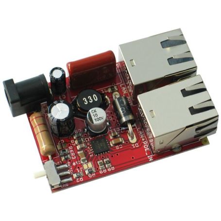
PoE adapter for 5V or 12V project
PoE for electronic projects
- IEEE 802.3af-2003 conform
- PoE injection >= 37V DC
- Output: 5 or 12V DC
- MOD-POE-v2
MOD-POE-V2 only works in Alternative B (Mode B).
Payments are secured by LyraCollect, a French payment collection company.
It is possible to delivered to your home, to a pick-up point or picked up by appointment at MCHobby
We prepare, pack and ship your orders with great respect and care.
Extract power from PoE network to power your project with 5V or 12V DC
The MOD-POE-V2 board extracts power from the UTP LAN cable network wired in Mode B. This module can power your embedded device with 5 or 12VDC.
Thank to this module, a single Ethernet cable can carry the power + Ethernet.
At the other end of the LAN cable, you must have a PoE-compatible switch/router.
The MOD-POE-V2 follows the recommendations set by IEEE 802.3af-2003 standard. The MOD-POE-V2 is not compatible with Olimex MOD-POE injector because it needs higher input voltage (at least 37V DC).
MOD-POE-V2 works only in Alternative B (Mode B).
No galvanic isolation
There is no galavanic isolation between MOD-POE-V2's power input and output! This might be a problem if your hardware setup has more than one source of power applied at the same time! Make sure to take precautions if your hardware setup has more than one power supply (or even only ground) attached!
Technical details
- Si3402 PoE controller with DC-DC step down converter and PoE protocol negotiation
- SiLabs Si3402 datasheet
- Power output: 5 or 12 VDC (switch selectable)
- Dimensions: (54 x 39)mm
- Operating temperature range: -40°C to +85°C
Tutorial
I provide 24V to the input of MOD-POE-V2 but there is no output. What is the problem?
Si3402 would NOT work with 24V DC. The recommended voltage is 48V DC and the minimum is around 37V DC. For more info refer to Si3402-B's datasheet.
What is the maximum current output approximately?
The maximum output is close to 10W. This means ~800mA for the 12V output mode; ~2000mA for the 5V output mode.
It seems my board get damaged by MOD-POE-V2. I have MOD-POE-V2 powered via PoE and it powers another board. This other board is sometimes connected to a personal computer via USB. What could have went wrong?
There is no galvanic isolation (no optocoupler, no transfoermer, etc) between MOD-POE-V2's power input and output! This might be a problem if your hardware setup have more than one source of power applied at the same time! If the board powered via MOD-POE-V2 is also connected to a different power supply that adds a second ground (for example, if it is connected to a computers USB port or another power source) - something may get damaged during the connection! Make sure to take precautions if your setup has more than one ground! It is good idea to disconnect the connections between MOD-POE-V2 and the target, power everything and measure the voltage difference between the grounds of MOD-POE-V2 and the target (before establish the connection). If the voltage difference is too high do NOT connect the target to MOD-POE-V2 and the other power supply at the same time. Maybe try adding optocoupler, maybe try connecting the grounds first before the power, etc.
Consider using Olimex USB-ISO to protect your computer and board from this accidental overvoltage.
Does MOD-POE-V2 work in both PoE modes - A and B?
No. By default MOD-POE-V2 works only in mode B - pins 4–5 form one side of the DC supply and pins 7–8 provide the return; these are the "spare" pairs in 10BASE-T and 100BASE-TX. Mode B requires a 4-pair cable.


