PICO 2 Breadboard
Pico / Pico 2 to breadboard adapter
- Connector for Pico / Pico2
- 5V rail
- 3.3V rail
- Reset button
- 2 user buttons
- 2 user LEDS
- I2C Grove conn.
- I2C Qwiic/StemmaQt conn.
Payments are secured by LyraCollect, a French payment collection company.
It is possible to delivered to your home, to a pick-up point or picked up by appointment at MCHobby
We prepare, pack and ship your orders with great respect and care.
Breadboard adapter for Raspberry-Pi Pico 1,2,W,etc
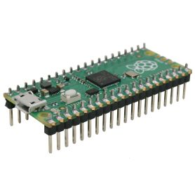
Here's an official Pico adapter (all versions) for breadboards, allowing for maximum space on the breadboard, leaving more than two rows of pins (which would be the case if the Pico were directly mounted on the breadboard).
This adapter offers other advantages:
- 5V rail. Injects 5V to a higher power rail. This voltage comes directly from the USB connector.
- 3V3 rail. Injects 3V3 to the lower supply rail. This voltage is produced by the Pico.
- Reset button. incredibly useful.
- Two user buttons wired on GPIO 16 and 17 (to be used with internal pull-up).
- Two user LEDs wired on GPIO 14 (red) and GPIO 15 (green)
- One Qwiic cnnector (SparkFun) / StemmaQT (Adafruit) shipping the I2C(1) bus.
- One I2C Grove connector shipping the same I2C(1) bus
Since the I2C bus(1) is located on GPIOs 6 (sda) and 7 (scl), the breadboard connector labels are replaced with "sda" and "scl."
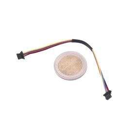
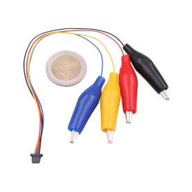
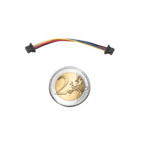
The Qwiic and Grove connectors allow you to easily connect I2C sensors and components to the microcontroler.
The board also provides two PCB jumpers (under the PCB) to free up GPIO 14 and 15 (the LEDs).
The board also features a three-position GROVE_PWR PCB jumper. This jumper is pre-configured for a 3V3 power supply.
To configure it for 5V, you'll need to cut the track between the 3V3 and the center, then place a solder bridge between the 5V and the center pad.
Finally, AGND is connected to GND via a PCB jumper.
Advanced users can adjust the analog filter circuit by cutting the trace in the PCB jumper THEN connecting the AGND ground to the breadboard.
Insert the adapter on a breadboard is quite simple, just place the connectors above the breadboard and press gently with your fingers.
Remove the adapter
Removing the adapter from the breadboard requires a little delicacy.
Indeed, the force required to extract the pins from the breadboard may be somewhat high.
Pulling on the Pico part is likely to damage the adapter at the shrinkage point. A choice was to be made between bulk and rigidity.
Place a round object, without sharp corners, under the connector (see product images) then gently lift the object to create a lever arm on the breadboard.
Repeat the operation on both sides of the connector to gently remove it from the breadboard.
Content
For each order you will receive an assembled and tested adapter.
Pico, breadboard and cables not included.
Tutorial
- Pico-2-BB (Github, MCHobby)
Useful ressources


