


MicroPython NADHAT HAT F405
NADHAT F405 - MicroPython board with Raspberry-Pi's compatible GPIO
- Drive PI's HAT with MicroPython
- Combinate Pi + MicroPython development on a single plateforme

Payments are secured by LyraCollect, a French payment collection company.

It is possible to delivered to your home, to a pick-up point or picked up by appointment at MCHobby

We prepare, pack and ship your orders with great respect and care.
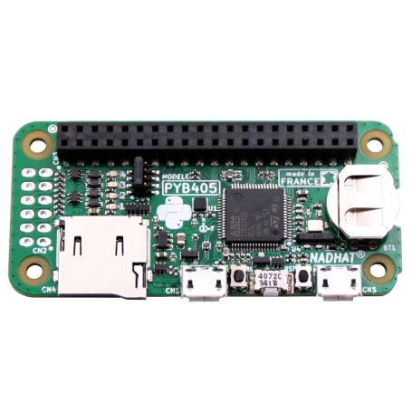
A MicroPython board with a GPIO Raspberry-Pi
When Garatronic discovered MicroPython and fell in love with it, Frédéric wondered what he could do for this work environment. And his thinking led to an interesting project, here is a MicroPython board as the Pyboard (same micro controller) but equipped with a GPIO Raspberry-Pi (2x20-pin).
It works like a MicroPython Pyboard but on a board with some interesting improvements. Everything that is learned about MicroPython Pyboard, see our Wiki, is therefore directly applicable to the PYB405.
The relationship with the Pyboard is undeniable... the PYB405 has all the standard elements of a quality MicroPython board:
- STM32F405RG processor (as on the MicroPython Pyboard),
- A 3-axis accelerometer,
- A support for micro SD card,
- A user button, reset button and DFU button (to update the firmware)
- 4 color LEDs
- A battery for the RTC clock.
- A micro USB connector (for programming and access to the file system)
- A second micro USB connector (for power only).
Frédéric didn't stop halfway! The standard pin functions of the GPIO Raspberry-Pi (Pi 3 B+) are all mapped to the corresponding pins of the NADHAT PYB405.
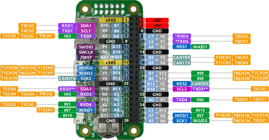
In addition, a jumper makes it possible to cross (or not) the RX/TX lines on the GPIO connector.
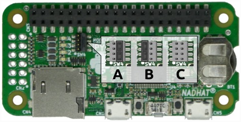
- Position A: Direct connection of RX/TX to allow the PYB405 to communicate with a HAT operating a UART (eg: HAT GPS or the NADHAT-GSM board).
- Position B: crossing RX/TX lines to allow a Raspberry-Pi and PYB405 to talk together on the UART.
- Position C: Disconnection of RX/TX lines between Pi and the PYB405 (or PYB405 and a HAT).
Several ways to use NADHAT PYB405
This approach allows to consider several use cases for this MicroPython NADHAT PYB405 board.
MicroPython development on Raspberry-Pi
Use the NADHAT PYB405 board to make MicroPython developments from a Raspberry-Pi Zero or a Pi.
This makes it possible to built a fully integrated MicroPython development environment, all you need to do is connect a monitor and a keyboard/mouse and let's go. In this case, the crossing of the RX/TX lines is indicated.
In this case, the NADHAT PYB405 board becomes a powerful micro controller that can be dedicated to specific tasks and, in this way, support a Raspberry-Pi in its higher-level tasks.
Exploiting HATs with MicroPython
Exposing a GPIO with Raspberry-Pi compatible functions is the opportunity to connect HATs on the NADHAT-PYB405 micro controller and with MicroPyhton. As the I2C, SPI and UART buses are well placed, it allows to exploit many HAT directly with the micro controller. As a result, the same HAT can be used in two different environments (on the Pi but also with the PYB405).
Make STM32 development with Raspberry-pi
Rather intended for advanced users, it is possible to prepare an OpenOCD development chaine on the Raspberry-Pi. This environment will download/upload and debug, from the Raspberry-Pi, the software developped for STM32. The Raspberry-Pi becomes a JTAG probe.
What's admirable in all this is that MicroPython itself is STM32 software and that, therefore, it becomes possible to debug it in SWD with a Raspberry-Pi :-)
Frédéric of Garatronic will certainly have the opportunity to write an article on this subject.
All this is made possible because the nRst pin of the micro controller is connected to pin 15 (GPIO 22) of the Raspberry-Pi. This spoils the GPIO compatibility that allows a Raspberry-Pi to reset the MicroPython board (a necessary evil for doing OpenOCD development).
A low profile GPIO connector = multi-functional connector
The board is equipped with a low profile female connector, a very good idea since it is possible to plug directly on the GPIO of the Raspberry-Pi.
The male connector delivered with the board allows to transform the low profile connector into a male connector to connect either HAT... or your own interfaces made on a Hat Perma Proto, a prototyping Hat springton (already designed for this application), a cobbler or any other interface type Raspberry-Pi.
And thanks to this connector, nothing prevents to combine the NADHAT with a stacking header, a GPIO replicator, and all these good things brought by the universe Raspberry-Pi.
CN2, the more tolerant input/output connector
The GPIO connector isn't the only good idea of the PYB405.
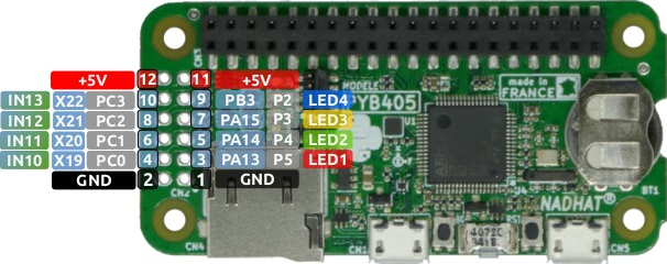
The board has a second 12-point connector named CN2 (next to the micro SD connector). This one offers:
- 4 tolerant 20-volt inputs
- 4 power outputs 100mA max
The 4 inputs are 16V tolerant named IN1 to IN4 are respectively connected to the inputs X19 to X22 (analog inputs of the MicroPython board). A voltage divider bridge with the resistances of 10K and 2.2K. So the input voltage is diveded by 5.54, making it possible to operate 12 V signals safely.
To convert the analog reading to voltage, use the following procedure:
adc = ADC('X19')
val = adc.read() # ex: val=1113
volt = 3.3 * (val/4095) * 5.54 # or 4.96 volts
The 4 outputs are open-collector transistors controlled by the 4 color LEDs. Either OUT1 to OUT4 respectively controlled by LED(1) to LED(4). Note also the colors of the LEDs which are respectively Red, Green, Orange, Blue.
# Enable output OUT1
pyb.LED(1).on()
# Disable output OUT3
pyb.LED(3).off()
An open-collector transistor acts "like a switch" to connect (or not) a peripheral/load to ground. It's a bit like cutting (or restoring) the power of a device by removing the wire connected to the negative pole of the power supply (I insist... the negative pole!).
A transistor makes it possible to control more powerful elements like motors or relays (attention: 100mA max!!!) and the fact that it is in open collector makes it possible to control these loads with a higher voltage like 12v (50v max!!).
Note that each of the transistors has a protection diode, also called "freewheel diode" (discussed in this tutorial). It is therefore possible to connect relays, motors and other inductive components without putting the transistor and the micro controller at risk.
USB connector
The PYB405 board has two micro USB connectors.
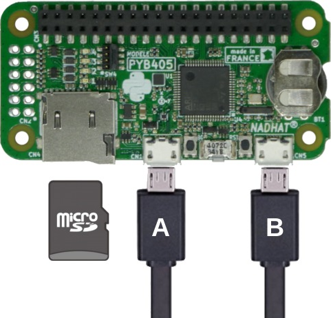
- Connector A: allows to power and program the PYB405 board from a computer. This connector allows the Pyboard to expose its files (scripts) using the MSC service, expose UART VCP (Virtual Com Port, serial port via USB) or as the HID service when it is enabled in boot.py.
It's also via this connector that a new Firmware is uploaded to the board. - Connector B: can be used with a USB power suply to power the board without locking connector A. In this way, it is possible to intervene on the MicroPython board (REPL, Debug, collect data) via connector A without interrupting the power supply provided via connector B.
Always on time
The PYB405, like the Pyboard, has a RTC clock to stay on time. But to stay on time, you need a battery to power the clock when the board is off.
This is good, the PYB405 has a connector for battery CR1225 and the button cell that goes with it.
If you use a tool like RShell (see the MicroPython tutorials on the Wiki) then this one will take care of updating the clock at each connection.
The buttons
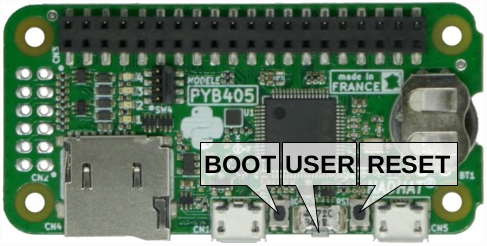
The PYB405 has three buttons:
- The reset button is used to restart the micro controller.
- The user button (pyb.Switch) is free to use
- The BOOT button is used to boot the board in DFU mode (Device Firmware Upgrade) to update the MicroPython firmware or upload your own STM32 firmware on the board.
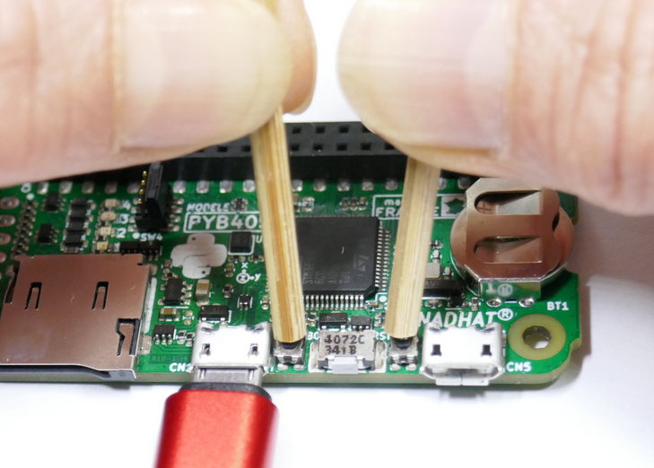
Note that to activate the DFU mode, press the BOOT button, press and release the RESET button and finally release the BOOT button. Feel free to use wooden skewers (insulating materials!) if the buttons don't seem easily accessible.
Content
For each order, you'll receive:
- The NAHDAT PYB405 board fully assembled and tested.
- A micro USB cable to start your experiments quickly.
- A CR1225 battery for RTC clock
- A row of 2x20-pin male connectors (to be placed on the GPIO connector... if you want to connect a HAT).
Technical details
- STM32F405RG processor (identical to MicroPython Pyboard),
- A 3-axis accelerometer,
- A support for microSD card,
- A user button, reset button and DFU button (to update the firmware)
- 4 color LEDs
- A battery for RTC clock.
- A micro USB connector (for programing and access to the file system)
- A second micro USB connector (for power only).
- pHat form factor (like the Pi Zero).
- 40-pin GPIO, with advanced compatibility with the Raspberry-Pi.
Resources
- Home Page of the PYB405 documentation (GitHub)
- GitHub NadHat PYB repository (GitHub Garatronic)
Schema of the board. - MicroPython repository for PYB405 (GitHub Garatronic)
Allows you to compile your own version of MicroPython for the PYB405. - Presentation of the NADHAT PYB405 (Garatronic)
MC Hobby also produces drivers to control sensors and interfaces with MicroPython boards.
These are made available
Tutorial and support
- MicroPython Firmware for Nadhat F405 (MicroPython.org)
- Garatronic Forums (forum.garatronic.fr)
- MicroPython Wiki (Wiki, MCHobby)
Everything you learn with the Pyboard will be usable on the NADHAT PYB405 :-)
It's the same heart.
- Raspberry Compatibility
- Zero / Zero W, Pi 3A, Pi 3B+, Pi 4, Pi 5, Zero 2 W
- Interface : Connector
- HAT (RPi GPIO)
- MCU : Programing
- MicroPython (CircuitPython)
- MCU : Family
- STM32
 for Raspberry-Pi")