

Timer + Charger board for Raspberry-Pi Pico
Timer expansion activating MCU + Lipo charger for Raspberry-Pi Pico
- Timer Mode (default)
- from 100ms to 2H
- configured via TrimPot - One-Time Mode (optional, with button)
- Control the Pico EN pin
- Done input
- Accu Lipo connector (JSP PH 2)
- Lipo Charger

Payments are secured by LyraCollect, a French payment collection company.

It is possible to delivered to your home, to a pick-up point or picked up by appointment at MCHobby

We prepare, pack and ship your orders with great respect and care.
PICO-TIMER-BOOT : Timer and Lipo charger for Raspberry-Pi Pico
Programmable Timer
The Pico-Timer-Boot is designed for battery-powered applications that does not need to operate continuously.
This applies, for example, to sensors placed around a house or in a garden shed—there is no need for them to be powered all times for collecting telemetry data.
In the facts, activating the device every 5 minutes, 15 minutes, or even once an hour is more than enough to capture data while preserving power with deepsleep pause.
The Raspberry Pi Pico is not energy-efficient (even in sleep mode) for considering battery only operation.
This board incorporates a TPL5111 in timer mode—a programmable timer able of triggering activation after a deepsleep time from 100ms to 2 hours—while consuming only 35nA (nano-amps).
The TPL5111 controls the Pico's EN (enable) signal, allowing its voltage regulator to be activated at timed intervals.
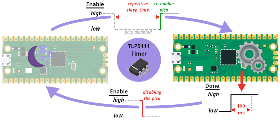
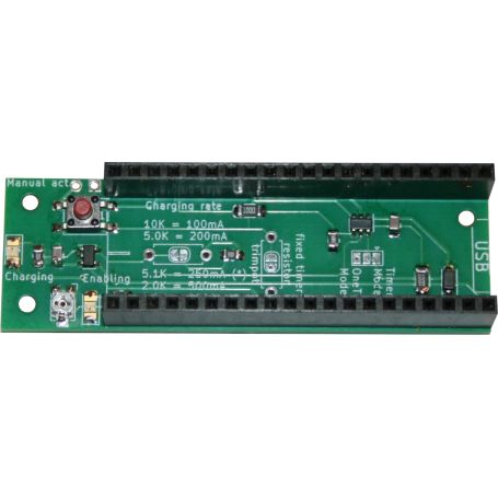
A green LED lights up when the timer activates the Pico.
This LED can be disabled by cutting the "En. LED" jumper located underside the board (near of the LED).
Once its task is complete, the Pico can inform the timer with a low-to-high DONE transition from pin GP13 (at least 100ms), prompting the TPL5111 into a new deep-sleep cycle.
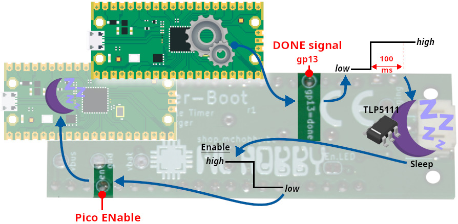
IF the microcontroller fails to signal the DONE completion of its task (via GP13) within a time frame equal to the sleep period THEN the timer will deactivate and immediately reactivate the Pico—effectively performing a reset.
The time duration is set using a potentiometer; its value can be read between the points surrounding the trimpot jumper.
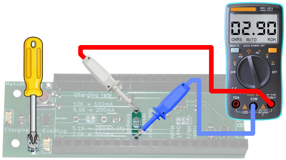
Here are some typical values:
| Pot. value | Time |
| 22K | 1 min |
| 29.3K | 2 min |
| 42.9K | 5 min |
| 57.5K | 10 min |
| 92.2K | 30 min |
| 124.9K | 1 hour |
| 170.0K | 2 hours |
For a duration in the range of 100ms, starts with 500 Ohms, then add 500 Ohms for every additional 100ms (i.e., 500 to 4500 Ohms for a time duration of 100ms to 900ms).
The Trimpot can also be replaced with an external potentiometer or a fixed resistor.
In such case, cut the Trimpot trace jumper, then solder your potentiometer/resistor to the two contacts onto the both side of the jumper.
One-Time mode
If you reconfigure the TLP5111 to "one-time" mode (see the 3-position jumper), the button can manually activate the TLP5111.
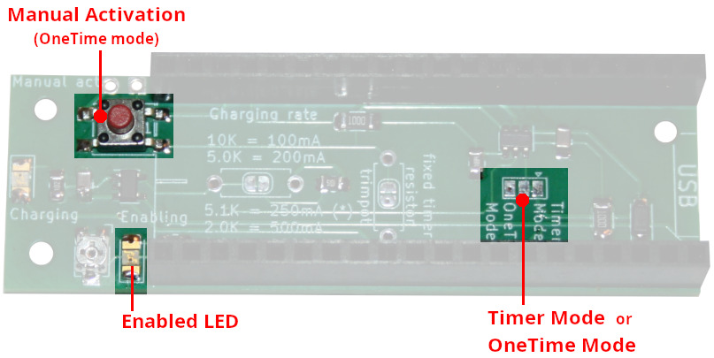
This allows user to power on a standalone project only when it is needed; the TLP5111 will then get a low-to-high DONE transition when it is time to deactivate the project. This approach is also well-suited for activating a project when a specific event occurs (e.g., a door opening).
This button/contact can be relocated using the breakout connector located right next to it..
Lipo Charger
The Pico + Pico-Timer-Boot assembly is powered by a LiPo battery connected to the standard JST-PH 2 connector.
The expansion is also fitted with a charge controller (for one cell) so that the battery is charged as soon as the Pico is plugged into a USB source.
The Yellow LED (near the Lipo connector) stays on during the charging process. This LED goes out once the battery is charged.
The charging current is 250mA. It can be modified by breaking the JP_PROG jumper and installing one fixed resistors.
Take care to stays below 1/2C charging current.
| Charging R | Charching current |
| 10K | 100mA |
| 5K | 200mA |
| 5.1K | 250mA * |
| 2K | 500mA |
| 1K | 1000mA |
Note that the TLP5111 timer continues its normal operation while the battery is charging.
For the makers
The board features 3x M2 mounting holes.
The silkscreen provides useful information (values for the timer and the battery charger).
The USB marking on the PCB indicates the orientation of the Pico.
This board can be used with other Pico expansions by using a Pico-Rack.
Independent of the programming language
The operating this board is independent of the programming language and does not require any library.
The GP13 pin is used to generate the DONE signal (powering down the Pico and re-enabling the timer).
The Pico-Timer-Boot controls the Pico's 3V3_EN pin, which allows the TPL5111 to power on the microcontroller.
Technical details
Timer
- TPL5111 in Timer mode (can be reconfigured in OneTime mode)
- Standby current: 35nA
- Timer: 100ms to 2H (via potentiometer)
- Potentiometer can be disabled via a breakable jumper and replaced with a fixed resistor or an external potentiometer.
- DONE signal on GP13 (low-to-high, 100ms)
- Manual activation button for OneTime mode (also available in breakout)
- Green LED : Pico activated (LED can be deactivated).
- Control the Pico EN signal (deactivates the voltage regulator).
- Independent of programming language.
- TPL511Technical datasheet (pdf, english)
Lipo charger
- LiPo JST PH 2 Lipo connector (also available on test points)
- Charging current 250mA (default, can be configured with split jumper + resistor)
- Automatic charging when connected over USB.
- Yellow LED : charging indicator (LED can be deactivated)
Other
- Power the Pico with the LiPo via VSYS pin
- Size: 61mm x 21mm (height12mm without Pico connector).
- Interface : Connector
- PICO
- Interface : Logic
- 3V