

Data Logger board for Raspberry-Pi Pico - PCF8523 & microSD
Data Logger for Raspberry-Pi Pico
- Real Time Clock RTC pcf8523
- MicroSD connector

Payments are secured by LyraCollect, a French payment collection company.

It is possible to delivered to your home, to a pick-up point or picked up by appointment at MCHobby

We prepare, pack and ship your orders with great respect and care.
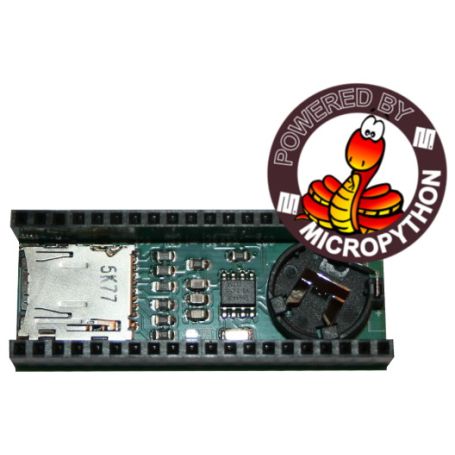
PICO-DATALOG-BOOT : real time clock and MicroSD reader for Raspberry-Pi Pico
The Pico or Pico 2 has relatively limited resources, which prevents its usage to handling intensive data logging or large files.
Thanks to this board, we have a useful microSD card connector that allows significant storage increase (we're talking gigabytes).
With MicroPython, a microSD can be mounted in the MicroPython filesystem with few instructions.
from machine import Pin, SPI
from os import VfsFat, mount, umount, listdir
from sdcard import SDCard

spi = SPI( 1, sck=Pin(10), mosi=Pin(11), miso=Pin(8), baudrate=0x14<<20)
cs = Pin(9,Pin.OUT, value=True )
sd_card = SDCARD( spi, cs )
vfs = VfsFat(sd_card)
mount( vfs, "/sd" )

print( 'dir /', os.listdir() )
print( 'dir /sd', os.listdir('/sd') )

# unmount the SD Card
umount( "/sd" )s
Having a real time clock is essential when doing data logging operation. So we added a RTC pfd8523 on board.
The clock have its own CR1220 battery backup, the battery will keeps the clock running event wihen the project is not powered.
Getting date and time from the pcf8523 clock is also possible with few lines of code.
As good practice, copy the RTC clock date time to the MCU internal clock.
i2c = I2C(1, sda=Pin(6), scl=Pin(7))
rtc = PCF8523( i2c )

_time = rtc.datetime
print( "Year: %s, month: %s, day: %s, hour: %s, min: %s, sec: %s, weekday: %s, yearday: %s" % time.localtime(_time) )
Signal Clock_out
The clkout/int pin is available on the clk_int jumper (back of the board).
This could be used to grab clock signal generated by the pcf8523. The available frequencies are: 32768,16384,8192,4096,1024,32, 1 Hertz or None.
See the test_clockout.py example script in the repository.
Alarm
The pcf8523 can handle alarm at fix date and time -OR- repetitive alarm (every days, every hour or so).
Once set, the clock can be query to check the alarm status.
See the test_alarm.py example of the repository.
Pico Wake-Up
Based on alarm, the clock can also manage a interrupt signal on the clkout/int output.
The pcf8523 output signal can be used to wake up the Pico from lightsleep mode.
Please note that clk_int jumper must be solder on the back of the board. That will allow the interrupt signal to reach the gp5 pin.
See the test_wakeup.py example of the repository.
Technical details
- PCF8223 Real Time Clock with alarm handling
- CR1220 Cell Coin connector
- MicroSD card Push-Push connector
- RTC interrupt on GP5 (not activated by default)
- SD Card detection on GP12 (actif by default, LOW=SDCard inserted, HIGH=Empty)
- Clock Out signal available on clk_int jumper (32768,16384,8192,4096,1024,32, 1 Hertz)
- Wake-up the pico via gp5 (clk_int jumper mist be soldered)
- Reset (pads)
Tutorials
- MicroPython support, schematic, examples available on GitHub (MCHobby, English/French)
- master.zip archive to quickly copy examples scripts and libraries on your MicroPython board
- Arduino support should be easy to find on internet.
- Interface : Connector
- PICO
- Interface : Bus
- I2C, SPI
- Interface : Logic
- 3V