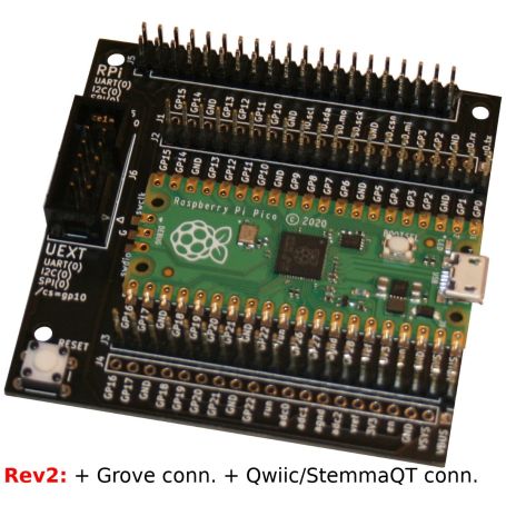


Pico-HAT r2: Hat Interface for Raspberry-Pi Pico
Control HATs and sensors from Your Raspberry-Pi Pico
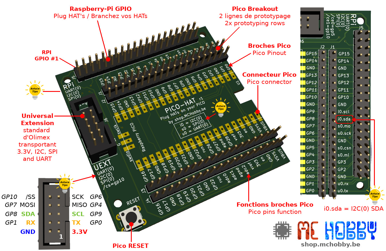
- Expose RPi GPIO header
- Expose UEXT connector
- Expose Grove, Qwiic, StemmaQT connectors
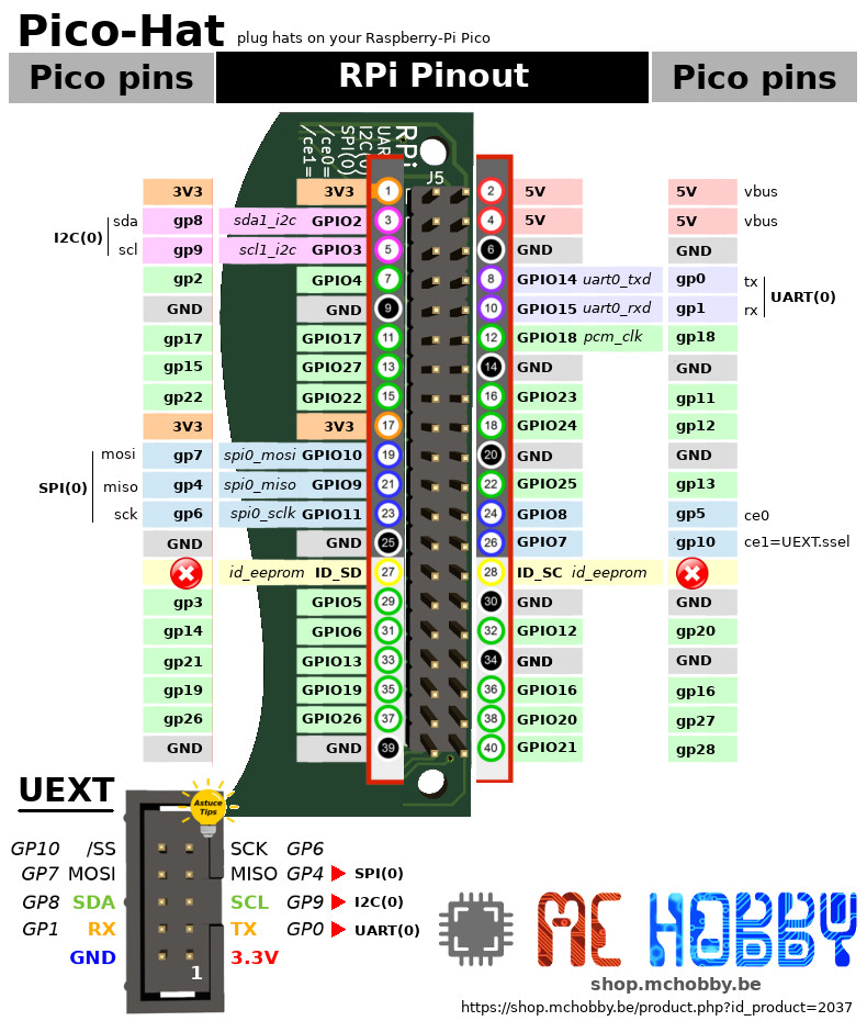
- Map UART, I2C, SPI buses
- Map Pico GPIO to RPi GPIO header
- Reset button
- Pico GPIOs replicat from prototyping

Payments are secured by LyraCollect, a French payment collection company.

It is possible to delivered to your home, to a pick-up point or picked up by appointment at MCHobby

We prepare, pack and ship your orders with great respect and care.
Pico-Hat... plug and drive HATs with your Pico
This interface board allows to re-use your existing Raspberry-Pi HATs with your Pico. So, you do not need to buy new devices/sensors for your Pico... just reuse existing board you already have.
Designed for STEM and learning, the PICO-HAT features:
- A double row to duplicates all the Pico's pins. Great for prototyping with the Pico.
- Every pin is labelled with the Pico Pico label and main pin function.
- Every IO on the RPi connectors is populated (main buses UART,SPI,I2C are attached to a corresponding Pico bus).
- The UEXT connector (robust and easy to wire) allows you to quicly plug expansion boards (relais board, sensors, LCD screen). See the UEXT line at MCHobby or UEXT line at Olimex. MCHobby does writes many MicroPython drivers for UEXT boards.
- I2C GROVE connector : powered with 5V, this connector allow you to plug Grove sensor using 3.3v logic for signals (eg: like the M5Stack Grove compatible sensor).
- I2C Qwiic/StemmaQT connectors : made respectively by SparkFun and Adafruit industries, this I2C did became popular in the USA. The connector power is confugered for 3.3V by defaut but this can be changed with associated solder jumper (just cup the 3.3V trace dans drop some solder to join the 5V rail.
The Pico board can be soldered directly onto the board but 20 pins female connectors (not included) can also be used to freely plug/unplug your pico from the board.
When prototyping + using HAT then you can also consider the usage of gpio expansion cable to move the HAT appart from the board while prototyping.
The best advantage of this Pico-HAT board is... its HAT compatible GPIO, an interface properly documented on the picture here below.
As we do have HATs availables, we did manage the MicroPython driver for some populars hats:
- Hat Sense : with MicroPython driver available here.
- Hat PiFace digital : with MicroPython driver available here.
- Hat motor : with MicroPython driver available here.
The Pico-Hat also allows you to use Grove device (3.3V logic), Qwiic from SparkFun or StemmaQT from Adafruit with your Pico.
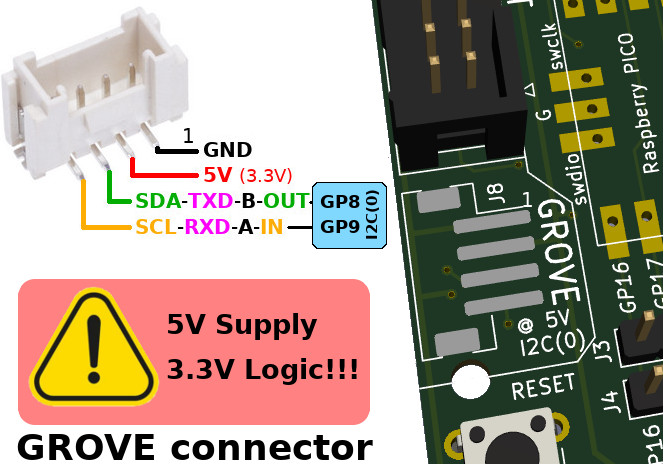
The board do have pads for Grove connector and pads for Qwiic/StemmaQT connector. Just solder them if you need them. Those connectors are wired to the Pico's I2C(0) bus so you can chain I2C capable sensors.
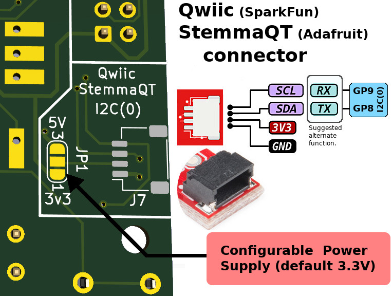
Of course, you can also drive the pins as digital IO but keep in mind that only one of the Grove / Qwiic interface could be used in such case.
Content
For each order, you will receive the Pico-Hat kit containing: the Pico-Hat board, a 2x20 pins connector (for the RPI GPIO), two full length pinHeaders (for prototyping) and an UEXT connector (10 pins IDC conn.).
The Raspberry-Pi Pico, Hats and GPIO's expansion ribbon are not included.
Solder tips
To make the assembly more easy, we do recommand to make it in a precise order. Just omit the steps if you don't want to use the target connector.
1) The Qwiic/StemmaQT connector
This connector is the smallest, we do advice you to start with this one.
Place it on the pads of the board and maintain it in place with some tool (the weight of some needle nose pliers may be sufficient to avoids the connector to move).
Place some flux just being the connector pins, this will help the solder to "wet" the pins.
Load you iron tip with some solder then gently drop it off on the pins.
Once the solder join cold, just repeat the operation with the mounting pads.
2) The GROVE connector
This connector is big enough to be keept with fingers.
As the Qwiic/StemmaQT connectors, start soldering the connector pads. This should be quite easy.
Once done, charge the iron tip with some fresh solder then solder the mounting pads on the both side of the connector.
3) UEXT connector
The third operation will be to solder the UEXT connector by taking care of its orientation. The connector knotch must be aligned with the silkscreen. Even if you don't want to use this connector, we do recommand to solder it anyway because it offers 2.54mm spacing connexion that may be useful for prototyping.
4) The RESET button
5) All the other components on the board

 - 2 cores microcontroler from Raspberry-Pi")
 - 2 cores microcontroler from Raspberry-Pi")
