MyDin - BackPlane 2 Relays for 3 modules DIN enclosure
Backplane board + Power
- For 3 modules DIN enclosure
- Power: AC
- 2 Relais - 5V 10A - NO contact
- 5V Vout
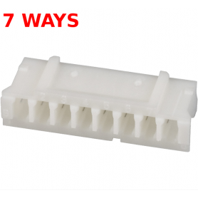
- MCU interface: JST PH 7
Secure payments
Payments are secured by LyraCollect, a French payment collection company.
Payments are secured by LyraCollect, a French payment collection company.
Multiple delivery solutions
It is possible to delivered to your home, to a pick-up point or picked up by appointment at MCHobby
It is possible to delivered to your home, to a pick-up point or picked up by appointment at MCHobby
Parcels packed with care and efficiency
We prepare, pack and ship your orders with great respect and care.
We prepare, pack and ship your orders with great respect and care.
2 relay backplane board for 3 modules DIN case
That backplane board offers:
- 2x 5V relay driving a current up to 10Amp from 2 digital signals (3.3V to 5V)
- Optocoupler protected
- AC/DC 5V 400mA onboard Power Supply Unit
The onboard power supply provides the 5 Volts required to operate the relays and the controller board. Controler are card equipped with a microcontroller (MCU) designed to drive this high power board (or any other). Check the Pico 2 Wireless controler for more information.
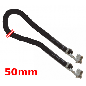
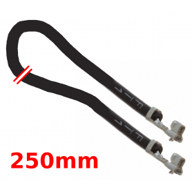
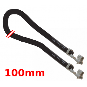
The backplane board features a standardized JST-PH 7 connector (see related products) allowing this backplane to be easily connected to the controller board (among the controllers we do offer or your own controller card).
This backplane connector is codified as follow:
| Pin | Direction | Description |
| 1 | PSU | GND |
| 2 | PSU | Output +5V ~100mA |
| 3 | Output | MCU_IN1 (not used, 3V3 signal input on the MCU) |
| 4 | Output | MCU_IN2 (not used, 3V3 signal input on the MCU) |
| 5 | input | MCU_OUT1 (3V3 signal. activates the relay REL1) |
| 6 | input | MCU_OUT2 (3V3 signal, activates the relay REL2) |
| 7 | input | MCU_OUT3 (not used, 3V3 signal) |
Tutoriel
- MyDin programming guide for Backplane and controler (MCHobby , Wiki, English)
- 2 Relay backplane documentation (MCHobby, Wiki, English)
Schematic, assembly and programming.
DINCASE-2R-BP3MOD
3232100027374
- Interface : Logic
- 3V
You might also like


