


Adafruit GPS MORE ULTIMATE - chipset PA1616D
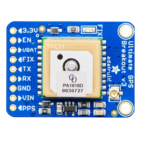
Adafruit Ultimate GPS Breakout Version 3
- 99 channels
- GPS + GLONASS
- frequency update at 10 Hz
- PA1616D

Payments are secured by LyraCollect, a French payment collection company.

It is possible to delivered to your home, to a pick-up point or picked up by appointment at MCHobby

We prepare, pack and ship your orders with great respect and care.
The More Ultimate GPS - one of the best GPS module on the market
Here is one of smallest best GPS module available on the market. This version of the GPS ultimate can use more networks (as GLONASS) to provide increased worlwide coverage. This is why Adafruit named this breakout version "MORE Ultimate". And it still consume raisonnable current (even if it is a bit more than the previous version).
With a signal sensitivity down to -165 dBm, a design supporting 5V, the 2.54mm spacing, refresh rate up to 10 Hz, 99 channels, the internal clock (RTC) with cell coin and the status LED the MORE ULTIMATE GPS bring all the need localisation feature to your project for less than 40 Euro TTC!
Compare to the MTK3339 used with the previous version, the PA1616D firmware is a bit different and existing projects would need some adaptation. See the details about "antenna query" for more information. The NMEA sentences also starts with $GN instead of $GP (when the GPS & GLONASS are available). The module do also have integrated datalogging capability inside the chip.
The breakout is made arount the MTK3333 hipset, a very high quality GNSS able to track 33 satellites over 99 channel. The high reception sensitivity (-165 dBm while tracking!) with the internal antenna. The module is capable to provide position update 10 times each seconds (10 Hz) for high speed tracking/data-logging applications. This module consume few power... only ~29 mA under navigation.
The board do have an ultra low dropout 3.3V regulator. Si this breakout can be powered with a voltage from 3.3V to 5V DC. The input pins are compatible with 5V logic. The ENABLE input pin allows to deactivate the GPS module by ising a switch or a microcontroler pin. The coin battery holder are used with CR1220 allowing to keeps the RTC clock alive (and counting the time while the GPS is powered off). A running RTC allow quicker warm restart.
The small RED led indicates the current status of the GPS. When the LED blink every second (1Hz) then the module do search for the satellites. When the LED blink every 15 seconds then the module did fix the GPS network (a blink every 15 sec do also spare energy). The signal is also made available on the FIX pin, so you can connect an external LED to it.
The PPS signal send a pulse of 50-100ms every second when the GPS gets a FIX. This signal can be used to to synchronize an external module.
The particularity of the MTK3333 is to allow to use an external antenna or an internal antenna (the patch ceramic offering a -165 dBm sebsitivity). Regarding the advanced feature, the modulle offers the autonomous datalogging feature. The µFl connector can be used to connect a 3V active GPS antenna (will be automatically detected by the GPS module). You will certainly needs to use a µFL to SMA adapter cable to wire the external antenna. We do have several kind of GPS antenna.
Adafruit propose a library for the GPS module (with background parsing capability). The library also allo to starts the DataLogging mode of the GPS (called LOCUS). A complete tutorial is aslso available for Arduino, CircuitPython and MicroPython.
What else to say:
- sensitivity -165 dBm, 10 Hz updates, 99 channels
- GPS + GLONASS support
- 5V friendly design and only 30mA current draw
- Breadboard friendly + two mounting holes
- RTC battery-compatible
- Built-in datalogging
- PPS output on fix
- Internal patch antenna + u.FL connector for external active antenna
- FIX LED
- External antenna support and Pulse-Per-Second output
- Status LED
The LED blink at 1Hz while searching for satellite.
The LED blink once every 15 secondes while fixed on the GPS satelittes. - FIX output
If you want the FIX status reported on the front panel (always on on FIX otherwise off) then you can use the FIX signal to light up an external LED. - PPS output: Pulse per Second.
Technical details
- Satellites: 33 tracking, 99 searching
- Patch Antenna Size: 15mm x 15mm x 4mm
- Update rate: 1 to 10 Hz
- Position Accuracy: < 3 meters (all GPS technology has about 3m accuracy)
- Velocity Accuracy: 0.1 meters/s
- Warm/cold start: 34 seconds
- Acquisition sensitivity: -145 dBm
- Tracking sensitivity: -165 dBm
- Maximum Velocity: 515m/s
- Vin range: 3.0-5.5VDC
- MTK3333 Operating current: 34mA acquision, 29 mA tracking
- Output: NMEA 0183, 9600 baud default, 3V logic level out, 5V-safe input
- DGPS/WAAS/EGNOS supported
- FCC E911 compliance and AGPS support (Offline mode : EPO valid up to 14 days )
- Up to 210 PRN channels
- Jammer detection and reduction
- Multi-path detection and compensation
- Weight: 8.5g (not including coin cell or holder)
- Dimensions: 25.5mm x 35mm x 6.5mm (not including coin cell or holder)
Tutorials
- Standard NMEA protocol, used by GPS modules to transmit their data.
See our wiki about NMEA protocol and commands (French). - See the Adafruit tutorial about GPS module (Adafruit, English).
Include reference to library and mode
Evaluation Board/Kit Important Notice
Adafruit Industries Ltd provides the enclosed product(s) under the following conditions:
This evaluation board/kit/module is intended for use for ENGINEERING DEVELOPMENT, DEMONSTRATION OR EVALUATION PURPOSES ONLY and is not considered by Adafruit Industries Ltd to be finished end-product fit for general consumer use. Persons handling the product must have electronics training and observe good engineering practice standards. As such the goods being provided are not intended to be complete in terms of required design-, marketing-, and/or manufacturing related protective considerations, including product safety and environmental measures typically found in the products that incorporate such semiconductor components or circuit boards. This evaluation board/kit/module does not fall within the scope of the European Union directives regarding electromagnetic compatibility, FCC, CE or UL and therefore may not meet the technical requirements of these directives or other related documents.
Creating a prototype with this evaluation board/kit/module must repect the applicable law in the country, including radio frequency regulations. Creating a product with this evaluation board/kit/module must also follows the applicable laws and regulations, the final assembly MUST BE CERTIFIED be certified accordingly to European RED directive and/or its translation in the local law.
The user assumes all responsibility and liability for proper and safe handling of the goods. Further the user indemnifies Adafruit Industries Ltd and MC Hobby SPRL from all claims arising from the handling or use of the goods. Due to the open construction of the product, it's the user responsibility to take any and all appropriate precautions with regard to electrostatic discharge, conducted and radiated emissions.
EXCEPT TO THE EXTENT OF THE INDEMNITY SET FORTH ABOVE NEITHER PARTY SHALL BE LIABLE TO THE OTHER FOR ANY INDIRECT SPECIAL INCIDENTAL OR CONSEQUENTIAL DAMAGES.


