

Photo transistor Light sensor
Photo Transistor Light sensor

Payments are secured by LyraCollect, a French payment collection company.

It is possible to delivered to your home, to a pick-up point or picked up by appointment at MCHobby

We prepare, pack and ship your orders with great respect and care.
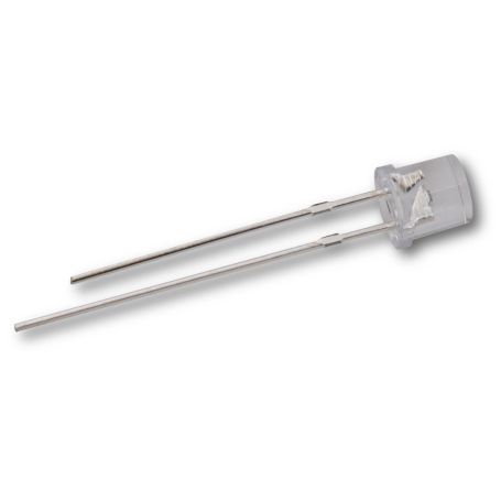
A light sensor to replace the photo-resistors (CdS)
This is a Photo Transistor Light Sensor which is a simple sensor that detects the ambient light. It is the opposite of a LED - it induces a current flow when the light hits the chip inside, the current flows from the long pin to the short. This sensor has a optical filter (probably IR filter, inside the LED) so the sensor would fairly simulate the human eye when evaluating the light level.
These are, essentially, replacements for CdS photocells, but are RoHS compliant.
How to use
Connect the pin connected to the 'thicker' part of the sensor to 3-15VDC. Then connect the thinner-part pin through a ~1K-10K series resistor to ground. The light level can be mesured with the voltage accros the resistor.
When its dark, there's almost no current flowing through the sensor. Then there is alsmost no current flowing inside the resistor and the resistor's analog voltage is near of the ground.
When there is light near the sensor, the current flow through the sensor. This current also flow through the resistor and raising the analog voltage accross the resistor.
You can adjust the series resistor to get the voltage range you need, and measure the analog voltage with a voltmeter. When inside the expected range (to not exceed the maximum voltage), you can wire it to an analog input of your microcontroleur.
If you do not get any reading/value, try flipping the sensor around to capture light.
Technical details
- Datasheet (pdf)
- Dimension: 5 x 5.3mm
- Weight: < 1gr