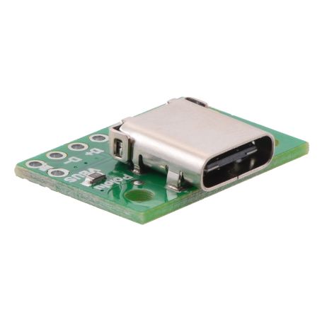


USB 2.0 Type-C Connector Breakout (USB-C)
USB 2.0 Type-C
- female connector
- Breakout board

Payments are secured by LyraCollect, a French payment collection company.

It is possible to delivered to your home, to a pick-up point or picked up by appointment at MCHobby

We prepare, pack and ship your orders with great respect and care.
An USB Type C in breakout with USB 2 data and configuration
USB C connector can cary a large variety of signals (it is really impressive!). This breakout board offer access to the power, USB 2.0 data, configuration and sideband pins of a USB Type-C connector with 2.54mm mm connexion. So, you can add USB Type C connectivity to your perfboards, breadboards and 2.54mm project plates. The beakout have pull-down resistors on configuration channel (CC) make it easy to use the receptacle in a power-sinking application.
The USB Type-C connector is designed to replace the wide range of existing USB connectors. It is reversible and can serve as USB host and USB device (allowing either end of the cable to be plugged into a receptacle with either side up) and it can support negotiation of increased power (up to 20 V and 5 A) and alternate uses of the USB interface wires.
The USB-C connector have 24 pins (tightly-spaced) making it difficult to use with hobby project or prototyping design.
This breakout board helps by offering access to:
- The connector’s pins for power (VBUS and GND),
- USB 2.0 differential data (D+ and D−),
- Configuration Channel (CC),
- Sideband Use (SBU).
Each of these pins is broken out into a 1×8 pins row (2.54mm spacing) on the board. The VBUS and GND pins are duplicated for high-current applications. The 1×10 male pinHeader (included) can be soldered to use the beakout with a breadboard or you can solder the your wires directly on it.
This board does not expose the Type-C connector’s USB 3.1 SuperSpeed differential pairs (TX and RX signals), so it only supports USB 2.0 Low-Speed, Full-Speed, and High-Speed communication.
Configuration pins
A Type-C can be used either to provide power as a “Source” or as power consumer as a “Sink”.
This usually corresponds to an USB host (Downstream Facing Port, or DFP) or as USB device (Upstream Facing Port, or UFP). The Configuration Channel, or CC, pins are used to determine the role of a port when it is connected.
This breakout board pulls the Channels configuration pins (CC1 and CC2 pins) to GND through with 5.11 kΩ termination resistors. This configure the port a Sink and a UFP by default (so a device consuming power).
With that Configuration Channel the breakout is a straightforward replacement for a Type-B, Mini-B or Micro-B connector on a USB device.
If you want to use the bearkout to source power (like USB Host) or if you want to perform advanced configuration like USB Power Delivery negotiation THEN you can disconnect or remove the on-board CC resistors and make your own connections to the CC pins (also exposed on the breakout).
Sideband Use pins
The Sideband Use pins (SBU for short) are not used by the USB protocol!
SBU pins are available after the USB interface configuration and SBU can operate in an Alternate Mode, which allows it to be repurposed for other protocols and applications.
This configuration is done through Communication Channel on the CC lines (between the host and device using the USB Power Delivery protocol).
Schematic and documentation
See the schematic is available in the product's pictures.
See the USB Type-C Specification for a description of the USB-C configuration process and other technical details.
This diagram is also available as a downloadable PDF: USB 2.0 Type-C Connector Breakout Board schematic