

ADXL335 - 3 axis accelerometer, analog output
ADXL335, 3 axis accelerometer
- +/-3G
- Analog output,
- 5V compatible

Payments are secured by LyraCollect, a French payment collection company.

It is possible to delivered to your home, to a pick-up point or picked up by appointment at MCHobby

We prepare, pack and ship your orders with great respect and care.
Detect object orientation or hurts
ADXL335 is a 3-axis accelerometer (Wikipedia) much appreciated because it's efficient and simple to implement. Since AdaFruit added a 3.3V regulator to it, this accelerometer has become compatible with Arduino or any other 5-volt microcontroller :-).
It's perfect for measuring static accelerations with high resolution (like a tilt type sensor). It's also suitable for measuring moderate accelerations during movement, shocks or vibrations.
Since our planet also has a gravitational acceleration (of 1G), it's possible to detect the orientation of the breakout relative to the earth with this sensor. Such an accelerometer can, for example, be used to detect the orientation of a phone screen (see this article on Wikipedia).
This will seem more obvious after reading the accelerometer calibration method (see tutorial).
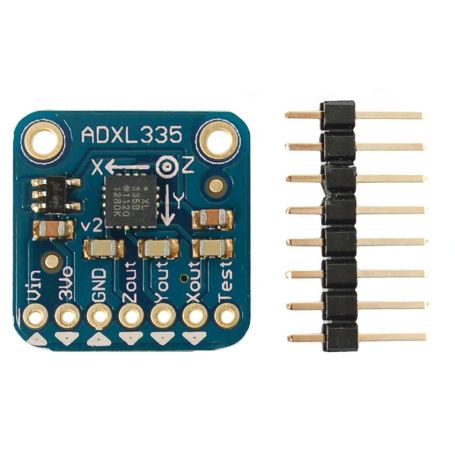
This 1.9cm x 1.9cm breakout has 3 analog outputs for measuring the X, Y and Z axes. The ADXL335 component is the latest from a family of analog components recognized for the quality of their MEMS peripherals (electromechanical microsystems Wikipedia).
The VCC terminal accepts up to 5V and regulates the voltage to 3.3V (voltage also available on an output pin).
Mounting on an Arduino
The analog outputs are of the ratiometric type (ratiometric: describing a system in which an output is directly proportional to an input).
The sensor being able to measure accelerations in both directions of the axes, the output voltage at 0g ("at rest" sensor) is right in the middle between 0 and 3.3v.
During a negative acceleration (say "forward" to simplify understanding) the voltage tends from 1.65v to 0 volts. During a positive acceleration in the other direction (understand "backwards" by analogy), the voltage tends from 1.65v to 3.3 volts.
This means that a measurement at 0g is always halfway between 3.3V (or 1.65V). At -3g the voltage is at 0v and at +3g the voltage is at 3.3V (with a homogeneous distribution between voltage and acceleration).
Content
Assembled and tested, this breakout board is delivered with a 2.54mm 8-pin pinHeader (not welded). This header will allow easy insertion into a breadboard or a prototyping plate. The breakout board has 2 fixing holes of 2mm for easy mounting.
The XYZ filtering capacities are 0.1uF for a bandwidth of 50 Hz.
The axes and their positive direction are indicated on the breakout board.
Technical details
- Length:19mm
- Width:19mm
- Height:3.14mm
- Weight:1.27g
- ADXL335 datasheet.
Tutoriel
- See our tutorial for Arduino in French (MCHobby Wiki)
")

