


2 UARTs HAT for Raspberry-Pi, NXP SC161S752
HAT 2x UARTs for Raspberry-Pi
- NXP SC161S752
- Hardware UARTs
- FIFO 64 bytes
- CTS/RTS

Payments are secured by LyraCollect, a French payment collection company.

It is possible to delivered to your home, to a pick-up point or picked up by appointment at MCHobby

We prepare, pack and ship your orders with great respect and care.
Adding UARTs on Raspberry-Pi made easy
If you had a Raspberry-Pi 4 then you already have several UARTs on the GPIO, it is not the same for the previous Raspberry-Pi's revision! Indeed, only one UART is not really confortable and on the Pi 3 B+ this is a Software UART (it's speed change with the SoC clock speed).
This pHat allows you to append 2 additionnal hardware UARTs (serial port) on your Raspberry-Pi 3 (or previous) or a Pi Zero by adding parameters to the /boot/config.txt file. A great option to extend the Pi 3/Pi Zero capabilities without the need to buy a Pi 4! This extension will perfectly suited for mobile, geolocalisation, domotic and industrial applications that appreciates serial ports.
Those UARTs devices are supported by the Linux kernel without software hack and are then accessible as any other linux devices from the /dev .
In this case, the UARTs will be available trough /dev/ttySC0 and /dev/ttySC1, they are fully operationnal and can be used with any Linux software.
If you have a NadHat GSM + Bluetooth board hten the 2xUARTs will allow to control the Bluetooth module (from the NadHat) to get paired with the Raspberry-Pi's Bluetooth. It is then possible to transport voice service between the the Raspberry-Pi and GSM module (via Bluetooth). The setup steps are described in this document made by Garatronic (TO LINK).
The earth of the board is propeled by a SC161S752 from NXP which can reach à maximum rate of 5 Mbit/s. This chip is connected to the Raspberry-Pi via the SPI interface. The 2 UARTs board has its own crystal so the transmission rate is totaly independant from the Raspberry-Pi's clock frequency. So you can take the advantage of the dynamic clock frequency (and power safe mode) on the Pi 3 B+ without distrubs the serial connexions.
the 2xUART board is the SPI1 interface on the GPIO so the SPI0 is still free for other common interfaces (eg: like TFT display).
Note: this module is also supported by Microsoft Windows IoT Core.
Technical details
You will find the NXP "SC161S752: Dual UART with I2C-bus/SPI interface" interface here under.
Some of those specifications are offers advanced features (such advanced feature maybe not supported by the Linux Kernel, they are reserved to skilled developpers).
- 2x Full Duplex UARTs
- 64 bytes FIFO (on RX & TX)
- Compatible with 16C450 industrial standard
- Up to 5 Mbit/s (with 16x clock mode)
- CTS/RTS automatic flow control
- Programmable Xon/Xoff automatic flow control
- Single or double Xon/Xoff characters
- Automatic support for RS-485 (automatic detection of the slave address)
- Up to 8 programmable input/output
- RS-485 direction control via the RTS signal
- NXP SC161S752 datasheet (pdf, anglais)
- Nadhat-2xUART board schematic (pdf, garatronic)
Used GPIOs:
- GPIO19 : MISO (ALT4)
- GPIO20 : MOSI (ALT4)
- GPIO21 : SCLK (ALT4)
- GPIO18 : SPI1_CE0_N
- GPIO24 : INT
Content
For each order, you will receive the 2xUART board.
The board does not includes stacking connector and spacers to keep the price as low as possible.
If you do not want to insert the 2xUART board directly on the Raspberry-Pi GPIO then we recommend to add a low profile stacking Header to your shopping basket.
Activate the 2 UART board
Case 1 : add 2 additional UARTs
Just need to add the overlay "dtoverlay=sc16is752-spi1.dtbo" in the file /boot/config.txt
# Load overlay for NadHAT 2xUART board
dtoverlay=sc16is752-spi1.dtbo
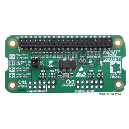
NOTE : for this configuration, the 2 jumpers JP1 & JP2 must be removed (the labelling should be obvious).
After rebooting, you can check the device availability with ls -lh /dev/ttySC* .
Case 2 : use the NadHAT V1 GSM and the Raspberry's BT 4.1
To use the Raspberry-Pi's Bluetooth, you will need to place the following directives under comment "dtoverlay=pi3-miniuart-bt" , "dtoverlay=pi3-disbable-bt"
# Release full uart /dev/ttyAMA0 for NadHAT v1 (no BT)
# dtoverlay=pi3-miniuart-bt
You will also need to disable the directive "ENABLE_UART=1", to put the value at 0
ENABLE_UART=0
NOTE : for this configuration, you will need to bring the first UART port to the 40 gpio header (pins 8=TX and 10=RX). The command "gpio readall" can be used to check the TXD and RXD pins, they must be set as input IN and not as ALT0 (UART mode). The two jumper can be inserted (vertical) on JP2 and JP3. The GPIO serial port is (/dev/ttyACM0) will be ttySC0. Nothing should be wired to CN1 (developpers can use this port to wire an logical analyser). The second serial port named CN2 is available to created externel serial connexion.

- Raspberry Compatibility
- Zero / Zero W, Pi 3A, Pi 3B+, Pi 4, Pi 400, Zero 2 W
- Interface : Connector
- HAT (RPi GPIO)
- Interface : Bus
- UART

