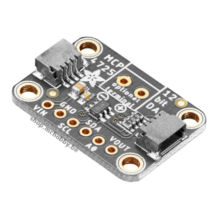
MCP4725 - digital/analog converter (DAC) - 12 bits - I2C interface
Numeric to analog converter for Microcontroler
- 12 bits résolution
- I2C Interface
- Breakout & Qwiic/StemmaQT con.
- A true analog output!!!
Payments are secured by LyraCollect, a French payment collection company.
It is possible to delivered to your home, to a pick-up point or picked up by appointment at MCHobby
We prepare, pack and ship your orders with great respect and care.
Add analog output to your microcontrler
Your microcontroler certainly have analog inputs (ADC = Analog to Digital Converter) but few microcontroler have analog outputs (DAC Digital to Analog Converter).
Arduino do not have native analog output.
This product will allow you to add an analog output to your project! The breakout is fitted with the MCP4725, a 12 bits DAC. The MCP4725 is easy to put at work thanks to the I2C bus used to configure it and set the output voltage. This simplicity make it easy to use such DAC with any microcontroler (Arduino, MicroPython, etc). Send the value over the I2C bus and the VOUT pin is set to the corresponding voltage.
This breakout is great for audio/analog based project where PWM control is not suitable. If you need for a true sinus or adjustable bias output signal then this DAC will make your wish come true.
This newer version of the DAC MCP4725 do expose Qwiic/StemmaQT connectors allowing quick wiring on boards also exposing such I2C connectivity. The breakout pins can be used when Qwiic/StemmaQt can't.
Technical details
The ADDR pin is available on the breakout, this can be used to change the I2C address on the bus. So it is possible to have TWO DACs on the same I2C bus (just wire the ADDDR pin of one DAC to HIGH level).
Work with 3.3v and 5v logic.
What's really great about this breakout are:
- It does handle FAST I2C bus @ 3.4Mbps (not with Arduino), so it is possible to update the VOUT signal at ~200 KHz.
- Does have an EEPROM. Si when you fix the output voltage then you can also store its value in the EEPROM... the voltage will be restored at next board power up ;-) .
- The output voltage is proportional to the supply voltage. The output voltage is rail-to-rail with the power voltage.
Rail-to-rail means the output voltage goes from 0V to output voltage (no voltage drop. When powered in 3.3V then output voltage will go from 0 to 3.3. When powered with 5V then the output voltage will go from 0 to 5V).
See also MCP4725 datasheet.
Wiring to an Arduino
Wiring is super simple:
- VDD to the microcontrôleur power (3-5V),
- GND to the ground,
- SDA to the I2C Data (Pin A4 on Arduino Uno, Pin 20 on Mega and Digital pin 1 on Leonardo),
- SCL to the I2C Clock (Pin A5 on Arduino Uno, Pin 21 on Mega and Digital pin 3 on Leonardo)
- check the VOUT voltage (with a voltmeter)


