

4 Channels Logic Level converter - Bi-Directionnal - I2C compatible
Logic converter 4-channels (4 bits) 3.3V 5V, bi-directional, compatible for bus I2C

Payments are secured by LyraCollect, a French payment collection company.

It is possible to delivered to your home, to a pick-up point or picked up by appointment at MCHobby

We prepare, pack and ship your orders with great respect and care.
Logical level shifter compatible with I2C, Serial, TTL
Here is a component known as "Level Shifter". It makes it possible to adapt the voltage of logic signals to make compatible, and in a secure way, Logic 5V and 3.3V.
Arduino (just like Basic Stamp) is a platform that works in 5 Volts while most modern sensors and displays, Flash card reader, etc only work under 3.3V. Therefore, it is necessary to use a component that converts the voltage from 5V to 3.3V and vice-versa.
In the same spirit, BeagleBone's GPIO's (inputs/outputs) are in 3.3V. It is better to use a voltage converter if you want to interface a BeagleBone with a logic or sensors operating under 5V. If it is possible to make direct connections according to the sensor and use case, it is better to remain cautious.
Using a Level Shifter protects the 3.3V hardware from the 5V voltage.
There are ready-to-use "Levels Shifters" components such as the 74LVC245 (DIP) or the super TXB0108 (also bi-directional). However, none of these two components operate in I2C which uses a particular pull-up system to send and receive data.
The "Level Shifter" that we propose combines the ease of use of the TXB0108 (bi-directional) with a FET design proposed by the company NXP and compatible with I2C.
As an example, using this component, you can design an I2C bus to coexist BeagleBone (Logic to 3.3V) and Arduinos (Logic 5V).
Technical details
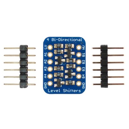
This breakout board uses 4 FET "BSS138" equipped with resistant pull-up of 10K.
It operates up to the 1.8V voltage on the low-voltage part (so called "Low Side"), and supports up to 10V on the high-voltage part (called "High Side").
The 10K resistor makes the interface a little less responsive than directly using a TXB0108 or a 74LVC245. If your project requires High-speed transfer, it is best to use these components directly.
This breakout is designed to provide I2C support, but it is also suitable for the SPI bus, TTL serial transfer and all digital interfaces. In uni-directional or bi-directional mode.
Delivered assembled and tested (except Pin Header). Contains 2 rows of 6 Pin-Header that you can solder to insert the converter on a prototyping board or a breadboard.
See also the data sheet of BSS138.
Tutorial
- The use of this breakout board is really simple.
Silkscreening explains how to make the connections as well as the connection of the voltage sources (see pictures). - Our tutorial HDMI server in French, turn a Raspberry Pi into an HDMI display server for Arduino... an affordable HDMI Shield.
- Our tutorial ArduPi-I2C in French (advanced user) allowing an Arduino Slave and a Raspberry Master to communicate via the I2C bus.
- The NXP application notes explain how this setup works (in English)
