


Sense HAT for Raspberry Pi
Sense Hat Astro-Pi - the "micro laboratory" ready to use

Payments are secured by LyraCollect, a French payment collection company.

It is possible to delivered to your home, to a pick-up point or picked up by appointment at MCHobby

We prepare, pack and ship your orders with great respect and care.
Hat Sense with sensors, display to learn coding on the Raspberry-Pi
The Hat Sense is a remarkable initiative from the project "Astro Pi" and offers an expansion card that embeds a series of sensors ready for use. A real lab waiting for your ideas.
The Hat Sense will be a tool of choice to animate Workshops, courses, interactive experiences, ... to discover the world of electronic hacking and its possibilities on the Raspberry Pi without having to make a connection.
The Hat Sense includes orientation sensors, magnetic, gyroscope, accelerometer, atmospheric pressure, humidity, temperature to perform many experiences, applications, human-machine interfaces and even games as well as an Atmel microcontroller.
You will be able to know the speed of your Pi, its orientation relative to the ground, the humidity rate of the air, the temperature, etc. The "Joystick" allows to interact with your programs.
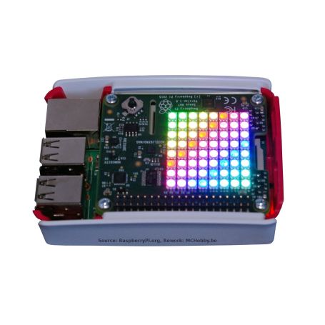
The Hat also has an 8x8 RGB LED matrix (a display) that allows you to display the data of the different sensors (in the form of scrolling text, graphics or other). With the magnetometer, you could create a compass indicating the magnetic north pole. You could also use the little joystick to make a Tetris, Ping or Snake game.
The Hat Sense is plugged into the GPIO port of the Raspberry-Pi using its 40-pin connector. This allows the Raspberry-Pi to power the Hat Sense and perform the data exchange. Once assembled, all you have to do is download the Python code and you have an "Astro Pi".
Writing programs for the Hat Sense is really very simple. The Hat has a Python library that allows you to start easily and quickly. The possibilities of projects around this Hat are numerous, you can get an idea of the possibilities by visiting the site astro-pi.org (English). You will also find lots of information and ideas.
When you buy this product, you receive a Hat Sense. The Raspberry-Pi, case and other items are not included (only used for illustrative purposes).
Tutorials
Here are some links to some documentation and tutorial around the Hat Sense.
MCHobby invested time and money to offer a "freely accessible" French translation. Thank you for supporting our efforts by purchasing your Sense Hat at MCHobby.
- The Astro Pi Guide (Wiki MCHobby, French)
All you need to know to get started with Hat Sense - A Guide to Astro Pi (RaspberryPi.Org, English)
The English and official version of the French translation that we propose. - This article from the Pi foundation.
- Examples Hat Sense (English, GitHub)
Examples relating to the Astro Pi competition - Astro Pi: your code in Space! (Astro-pi, GitHub, English)
Examples and projects - Sense HAT with microcontroler under MicroPython (MCHobby, GitHub)
Crispy details
- Gyroscope - angular rate sensor : +/-245/500/2000dps (dps = degrees per second)
It is used to detect changes in orientation (rotation around an axis) or change of rotation speed. It will detect pitch or roll. On a helicopter, it can detect the rotation of the tail... and thus the adjustment of the anti-torque rotor speed on the tail of the aircraft... history of flying straight. - Accelerometer - linear acceleration sensor: +/-2/4/8/16 G
Detects the acceleration / deceleration of an object. Able to measure the Earth's acceleration (which goes to the center of the earth) with respect to the 3 axes of the sensor. So you can also determine the position of the sensor relative to the ground. This is how phones know if their screen is facing the table (say face down) and goes to silent mode (see Samsung Galaxy). - Magnetometer - magnetic sensor, +/- 4/8/12/16 Gauss
Detects the magnetic field, whether it is generated by earth or electrical equipment. - Barometer - absolute pressure measurement from 260 to 1260 hPa.
The accuracy depends on the temperature and pressure, +/- 0.1 hPa under normal conditions.
Such a tool can be used to detect changes in barometric pressure... and therefore an element for predicting time. As the pressure also decreases with the altitude, it makes it possible to evaluate "roughly" the altitude with which the sensor is located (attention: precision of the order of the meter... at the best) - Temperature sensor - accuracy of +/- 2 degrees Celsius between 0 and 65 degrees Celsius.
Note that the sensor is near your Raspberry-Pi and the temperature of the Raspberry-Pi changes depending on the CPU load. Temperature measurements can therefore be influenced by the temperature of your Raspberry-Pi. - Humidity sensor - measures relative humidity, accuracy of +/- 4.5% in a humidity range of 20 to 80% humidity. Accuracy of +/- 0.5 degree Celsius in a temperature range of 15 to 40°C
- Display matrix - 8x8 LED
- Small joystick - 4 directions (with contact) + 5th contact (pressure on the joystick).
Technical specifications
Temperature sensor
- LPS25H from ST Micro
- Pressure measurement - 24-bit resolution - 260 hPa at 1260 hPa
- Temperature measurement - 16-bit resolution - 0 to 125 °C
- Technical data sheet
Humidity sensor
- HTS221 from ST Micro
- Humidity measurement - 16-bit resolution - 0 to 100% relative humidity
- Temperature measurement - 16-bit resolution - 0 to 60 °c
- Technical data sheet
Accelerometer / Gyroscope / Magnetic Field
- LSM9DS from ST Micro
- 9 degrees of freedom (X,Y,Z axes independent for all sensors)
- Acceleration measurement range: +/- 16g
- Magnetometer measurement range: +/- 16 Gauss
- Gyroscope measurement range: +/- 2000 dps (degrees per second)
- Resolution: 16 bits (for each measurement channel)
- Technical data sheet
These sensors have the characteristic of periodic sampling of the sensor values - with internal FIFO storage. The LPS25H and HTS221 have a maximum sampling rate of 25 measurements per second, the LSM9DS1 has a maximum sampling rate of 952Hz - These features would be sufficient (cf this article from the Pi foundation) to consider the birth of quadcopters controlled by Raspberry-Pi.
LED matrix
The LED matrix is based on RGB LEDs equipped with a constant current controller to ensure beautiful colors... even when the voltage varies. LEDs are controlled by an Atmel ATTiny88 microcontroller well known in the Arduino world. The Firmware allows to control 8x8 RGB LEDs with a resolution of 15 bits.
For those who want more details, the AVR firmware is available on the GitGub of the Pi foundation.
The LED matrix is refreshed at the frequency of 80 Hz.
As a bonus, the LED matrix is also recognized as a FrameBuffer device.
You can send data directly to the FrameBuffer. So try the command:
cat /dev/urandom > /dev/fb1
Joystick
The Atmel microcontroller is responsible for sampling the joystick. The sampling of the joystick is combined with the selection of the lines of of the LED matrix. Therefore, the joystick is also sampled at 80 Hz.
The joystick is also accessible as a standard input device. The different positions of the joystick produce the keyboard inputs Up /Down /Left /Right and Return keyboard.
Atmel ATTiny88 microcontroller
The microcontroller is responsible for controlling the LED matrix and sampling the joystick.
The Atmel SPI bus is connected to the SPI interface of the Raspberry-Pi, so it is possible to reprogram the microcontroller from the Raspberry-Pi (it is also this SPI bus that is used to program the ATTiny 88 during the production phase.
The firmware of the ATTiny88 is interfaced on the I2C bus like other sensors.
I2C bus from Raspberry-Pi
All sensors are connected directly to the I2C bus of your Raspberry-Pi. These sensors are therefore directly accessible from the operating system and Python (as is the case for all other I2C sensors).
The basic firmware of Atmel88 is also accessible on the I2C bus, so you can talk directly with it if you feel like it.
SPI bus from Raspberry-Pi
The SPi bus of the ATTiny88 is connected to the SPI interface of your Raspberry-Pi.
See, above, information about the microcontroller.
Hacking
Turn off the I2C bus
The good thing about the I2C bus is that you can also connect other I2C devices.
Among the most useful, there is certainly a clock RTC to display the time ;-)
As you will have noticed, the GPIO connector is completely occupied, you can nevertheless recover and extend your I2C bus by welding wires on the following "test points":
- PP9 = SDA (I2C Data)
- PP8 = SCL (I2C Clock)
- PP13 = GND
Need tension, you will find it here:
- PP14 = +5V
- PP5 = +3.3V (will be more difficult to weld because close to the GPIO).
- Raspberry Compatibility
- Zero / Zero W, Pi 3A, Pi 3B+, Pi 4, Pi 400/500, Pi 5, Zero 2 W
- Interface : Connector
- HAT (RPi GPIO)