

RS485 communication module, not isolated, UEXT
RS232 to RS485 converter
- Supply: 3.3V
- Half duplex
- 250 kbps
- UEXT Interface

Payments are secured by LyraCollect, a French payment collection company.

It is possible to delivered to your home, to a pick-up point or picked up by appointment at MCHobby

We prepare, pack and ship your orders with great respect and care.
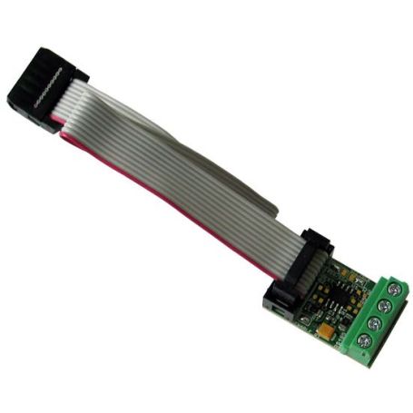
RS485 adapter
This board is the MOD-RS485 communication board from Olimex designed for MCU and nano-computer.
Based on the ADM3483ARZ from Analog Devices, this board is a small, low power, differential line transceiver designed to operate using a single 3.3 V and allows half-duplex communication.
This module can be used to convert RS232 signals into RS485 signals. It is an excellent choice for conveying information over long distances (1200m according to scpecs) and allows error-free data transmission at data rates up to 250 kbps.
The board can be wired to microcontroler with Dupont wires or you can use an UEXT cable (for UEXT capable boards).
The module uses UART interface + 2 control pins to establish connection to the host board (see tge schematic in product images). All required signals are available at the UEXT header.
More information on the manufacturer product sheet.
Wiring tips & tricks
Question: I can't establish proper connection to the board. What do I do wrong?
MOD-RS485 uses data UART signals (pins #3 and #4 of the UEXT) and two control signals (by default pins 9 and 10 of the UEXT).
You can't skip using the control singals that define whether you transmit data to RS485 lines or receive data from the RS485 lines. Completly disconnecting the control signals (SCL/SCK and #SS/SDA) is also a bad idea. The control signals are digital lines.
To use half-duplex communication:
- to send data set both SCK (pin #9) and #SS (pin #10) to high level. Send your data and check if it was successfully sent.
- to receive data set both SCK and #SS to low level.
Check the wiring of ADM3483ARZ in the MOD-RS485 schematic and read the description of the signals in the data sheet of ADM3483ARZ for more information.
Question: Can't use the I2C interface when MOD-RS485 is plugged! What's wrong?
Despite what it might look like - MOD-RS485 does NOT use I2C interface but the pin 9 & 10 from the SPI interface (the default setup).
See the previous question to know how to drive them (these two pins are connected to the ADM3483ARZ’s signals "DE" driver output enable and "/RE" receiver enable).
However, it is possible to change the default behavior. The jumper #SS/SDA and SCL/SCK can reroute the signals to pin 5 (SCL) and pin 6 (SDA) to control the RS485 flux. This is probably the case for your board.
When using the SCL and SDA pins to control the RS485 communication. In such case, the Pin 5 and Pin 6 of the UEXT connector are controled as digital I/O and no I2C communication could table place on the I2C bus.
Technical details
- Supply: 3.3V
- Half duplex
- Up to 250 kbps
- UEXT Interface (uart + 2 I/O)
- ADM3483ARZ datasheet (pdf, Analog devices)
Tutorial
- Arduino Example (Olimex, English)
- RS485 on Wikipedia (English)