


4 relays modules
Control module with FOUR relay + optocoupler ready to use for Arduino or Raspberry

Payments are secured by LyraCollect, a French payment collection company.

It is possible to delivered to your home, to a pick-up point or picked up by appointment at MCHobby

We prepare, pack and ship your orders with great respect and care.
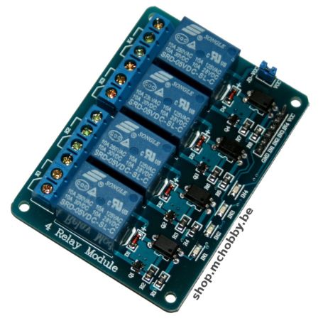
A 4 relays module ready to use with microcontroler's based projects
This module provides all the necessary functionalities for a fast implementation but especially four relays able to support 10A under 250V AC. What we appreciate most is the protection offered by Optocoupler and the possibility of dissociating the relay power circuit (JD-VSS) from that of the control logic (VCC)... it is enough to remove the jumper JD-VSS and to power the 5V relays through the JD-VCC pin.
Practical, it will offer a galvanic isolation (the high-voltage circuit is never in contact with the control circuit) as well as a protection for your electronic control circuit (in case of short-circuit, your microcontroller is protected electrically).
Description
The four relay double-throw module makes it possible to independently and easily control the equivalent of double throw single-pole switches from a low voltage signal and low control current. These relays are called "SPDT" for "single pole double throw".
This module uses relays powered by 5V and the card is fully assembled.
The card is equipped with standard 2.54mm impaction pins (like breadboards) which allows you to take control of the card with molex connectors or suitable connectors (see our wire assortment). Relay power contacts are routed to 5mm 3-way terminal block.
The card is equipped with 4 mounting holes 3mm in diameter.
Usage
To activate an RX relay, we must place the corresponding INx pin to the ground.
If the potential is not grounded by your microcontroller, the voltage is brought back to 4.7~4.8 volts (or ~3.3V if you power the VCC card in 3.3V).
Caution: do NOT connect an INx pin directly to a Raspberry-Pi (or other 3.3V microcontroller) with the JD-VCC jumper in place. Indeed INx pin would apply a voltage of 4.7 Volts on a card 3.3 Volts (Gloups!).
To use this card on a 3.3V system, it is absolutely necessary to remove the JD-VCC jumper then supply the relays in 5V via JD-VCC and the control logic in 3.3V via VCC.
Technical characteristics
- Compact module.
- Indicator LEDs for relay status.
- Use of freewheeling diode to avoid transient effects of coils.
- Each relay enabled consumes 63mA on the power supply (VCC)
- Activation current by control pin.
With a VCC relay power supply=5V- VCC = 5 Volts => activation current = 2.5 mA (by return to ground)
- VCC = 3.3 Volts => activation current = 0.4 mA (by return to ground)
High voltage use
This product does not have specific certification for use in high voltage environment. Working with a voltage higher than 30V can be extremely dangerous and should be reserved for people who are qualified to work in such conditions. It is necessary to use appropriate equipment and to apply adequate safety rules.
Tutorials
- Our Wiki contains a French page dedicated to relays and relay module.
Shows how to use this module with Arduino and 3.3V systems like the Raspberry-Pi