


[T] - Regulator 9V 600mA, Step Up, U3V12F9
Switching regulator U3V12F9, 9V, Step-up

Payments are secured by LyraCollect, a French payment collection company.

It is possible to delivered to your home, to a pick-up point or picked up by appointment at MCHobby

We prepare, pack and ship your orders with great respect and care.
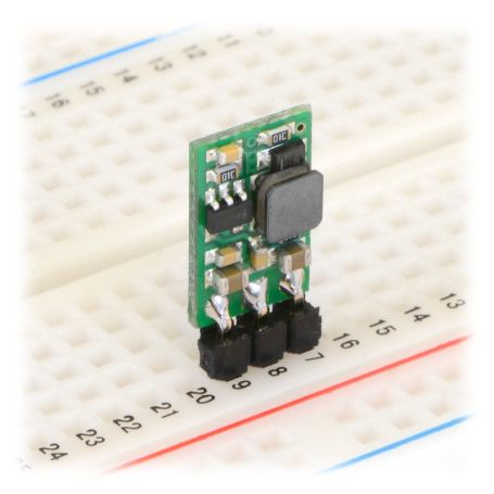
9V regulator (DC-DC chopper, U3V12F9) with input current of 1.4A max
The U3V12F9 step-up (or boost) switching voltage regulator produces a 9 V voltage from a power source between 2.5 V and VOUT (therefore 9 V in this case). These switching regulators are commonly called DC-to-DC regulator, Switched Mode Power Supply (SMPS) or switching regulator.
This regulator has an efficiency between 80 and 90% and is more efficient than a linear voltage regulator ... especially since the voltage difference between the input and the output is large.
The current available at the output depends mainly on the voltage available at the input. The current available at the output is approximately equal to the ratio of the input voltage divided by the output voltage. The greater the voltage difference, the more the converter needs a current on the input to produce the output voltage. If the input current exceeds the converter limit (somewhere between 1.4A), the output voltage will start to drop significantly.
Step-up, Step-Down ... What about them?
These are characteristics of switching voltage regulators. A Step-Up regulator is capable of increasing the voltage to reach the desired voltage. A Step-Down regulator will be able to manage a higher input voltage in order to reach the desired voltage.
A Step-up/Step-Down regulator is capable of reaching the desired voltage from a lower or higher supply voltage. This last model is practical if you need to keep a project powered up for as long as possible with a power source whose voltage drops over time (ex: battery).
Characteristics
- Input voltage: 2.5V to VOUT (9V)
- Output Voltage: fixed at 9V accuracy of +4%
- Switch of 1.4A: authorizes an input current up to 1400mA
- Standby current of 2mA (typical when there is no load).
- Overload protection (by cutout).
- Size: 13 × 10 × 3 mm
- Output current: depends on the input voltage! Between 150 and 800mA MAX (see graphics!)
Use the regulator
During operation of the regulator, the temperature may become high enough to burn you. Be careful when handling this product and those connected to it.
Connection
The regulator has 3 connections labeled on the back of the board:
- VIN: the input voltage.
- GND: the common ground at the input and at the output.
- VOUT: the output voltage.
VIN: The input voltage, must be at least 2.5 V and should not exceed the output voltage. Be aware of the overvoltage caused by LC type circuits (which can cause a VIN voltage greater than VOut).
VOUT: Output voltage.
efficiency and output current
The efficiency of the voltage regulator is defined as (Output power)/(Input power). This is an important measure to evaluate performance especially if the life of the battery or the heat generation are critical elements for your project. As the graph below shows, this regulator has an efficiency between 85% and 95%. The energy saving characteristics make it possible to maintain this very high efficiency even when the current is very low.
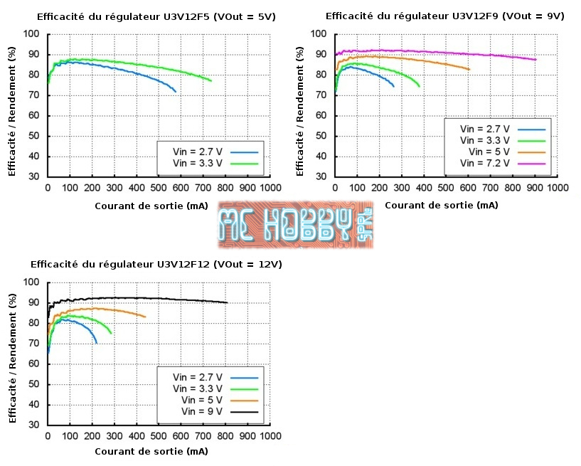
The maximum current that can be obtained from the board is approximately proportional to the ratio between the input voltage and the output voltage. If the input current exceeds the capacity of the DC-DC chopper (typically between 1.4 and 2 A), the output voltage will start to drop. In addition, the maximum output current depends on other factors including ambient temperature, air circulation and heat dissipation.
Overvoltage peaks caused by LC circuits
When you connect the voltage to an electronic circuit, the initial current draw can cause an overvoltage peak which can be much higher than the input voltage. The regulator can be destroyed if these overvoltage peaks exceed the maximum authorized voltage. If you use connection wires of approximately 50 cm and connect a power supply of approximately 20V then you could obtain overvoltages per LC circuit which can exceed 42V. If you use a power supply of more than 20v or a high inductance power supply, we recommend welding a capacity of 33 μF or large electrolytic capacity near the regulator between VIN and GND. The capacity must be able to support a voltage of at least 50 V.
You will find more information on LC overvoltages in the pololu application notes see "Understanding Destructive LC Voltage Spikes".