


Ludik-Hat - a HAT designed to discover electronics and programming with Raspberry-Pi
A HAT to discover electronic and programming on the Raspberry-Pi
- Experimentation center for Raspberry-Pi
- Ready to use
- No soldering required

Payments are secured by LyraCollect, a French payment collection company.

It is possible to delivered to your home, to a pick-up point or picked up by appointment at MCHobby

We prepare, pack and ship your orders with great respect and care.
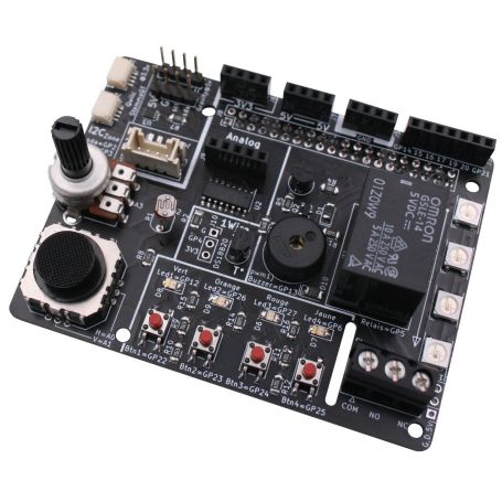
Electronic and programming discovery with the Raspberry-Pi with Ludik-HAT
Ludik HAT for Raspberry-Pi is intended for learning electronics and programming without having to take care about the wiring on the prototyping board or using the solder iron.
Connect it to your Raspberry-Pi GPIO then start experimenting... and let's leave the electronic prototyping/assembling to later :-)
Make in collaboration with François Mocq (Framboise314) and MCHobby, this Ludik HAT can be programmed with:
- Python,
- Scratch (still to do),
- C++
- MicroPython (with help of Pico-Hat)
The history behind this HAT?
When François from Framboise314.fr runs Arduino sessions, he does use a multifunction board that brought together on a single circuit everything needed to learn how to program the microcontroler. Such board is enough to animate a day of training with digital, analog, displays... François dreamed of an equivalent for the Raspberry Pi (without really finding the ideal tool).
So we did finally discuss the subject at a Maker Fair... and thus the Ludik Hat dir born.
What can we do with the Ludik Hat?
The Ludik Hat will allows to discover many aspect of the Raspberry-Pi GPIO programming as well as electronic skills.
Numerous training scenario with interactions facilities can be made with the Ludik Hat. Experiment can be driven with Python, Scratch or C.
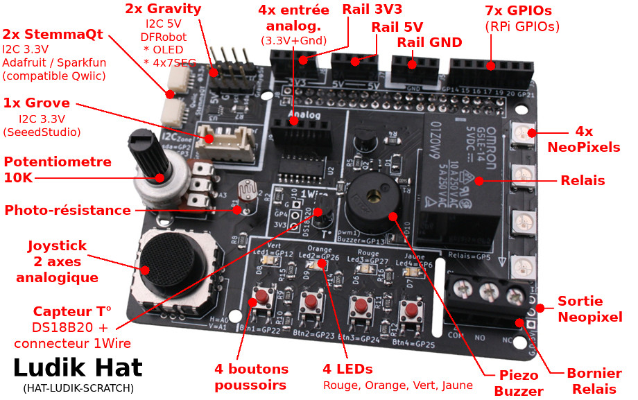
- 4 input buttons (great quality push button)
- 4 LEDs output (green, orange, red, yellow)
- 4 analog inputs directly wired on the following devices:
- A potentiometer
- A photo-resistor
- A 2 axis analog joystick
- 4 analog inputs (free for use)
- A relay
- A piezo buzzer to make sound
- 4 RGB LEDs also named "Neopixels" driven with 5 volts for max of luminescence.
- 1 digital temperature sensor (DS18B20, 1 Wire) together with additionnal connector (for adding others 1 Wires sensors).
- A 7 pin GPIO connector (free for use)
- Power output connexions: 3.3V, 5V, Masse/GND
- Various expansion ports:
- 2x StemmaQt (Adafruit) / Qwiic (SparkFun)
- 2x Gravity connector (5V, DFRobot)
- 1x Grove connector (3.3V, SeeedStudio or M5Stack)
Thanks to the various expansion port, you will be able to connect ready to use modules/sensors to your board. The expansion port exposes the I2C bus which is a very easy to use (4 wires only), chainable by design and many maker sensors/actuator board do using it.
Thanks to I2C bus, it is quite easy to read humidity in the air, athmospheric pressire, luminosity, UV level and many other environmental parameter..
The I2C bus can also be used to append OLED display screen, LCD display, 4x7 segments, etc.
Properly documented
The Ludik-Hat is not sold with "good luck" wish.
Instead, we did produced a multi-level documentation to help you in using the board.
Level 1: documentation and examples
The Ludik-Hat board is fully documented on the Ludik-Hat github repository. Currently in French
Level 2: auto-documented board
When looking the ludik hat SilkScreen, every sensors and connexion points are showing the Raspberry-Pi GPIO used.
By example, looking the second button you will see a label indicating the GPIO23. The RED LED is wired on GPIO27, the relay on GPIO5, and RGB LEDs (NeoPixel) on the GPIO18, and so on.
The analog sensors indicates which of the analog input is used on the analog/digital converter (MPC3008). So by looking on the board, you can notice that potentiometer is wired on the A3 input.
Level 3: le schematic
Always useful, thanks to the schematic you can identify the wiring between the components. If you are new in the Maker world this may appears a bit impressive but this will get more familiar with the time. Reading schematic do allow to quickly identify connexion and can make you spare lot of time.
The expansion ports
The selection of expansion port used on this board allows to plug boards comming from DFRobot, SeeedStudio, M5Stacks, Adafruit Industries, SparkFun Electronics and other manufacturer using the same connexion.
All the expansion ports are in the I2C area since it expose the Raspberry-Pi I2C bus, so GPIO2=SDA and GPIO3=SCL. You can also use those pins as digital IO but that would be a waste of useful ressource.
If you need to get more confident with such specific connectors you can read their description onto the MCHobby Wiki.
Gravity connector - 5V:
The Gravity interface was created by DFRobot and looks like 4 pins header having a 2.54mm spacing (like prototyping board).
This connector usually use 5V power, so we added a level shifter to bring signal from 3.3V to 5V. Si this connector is safe to use Arduino UNO sensors :-)
We do also have Gravity sensors on our shop but you can also find them on DFRobot webshop.
Grove Connector - 3.3V:
The Grove connector as been created by SeeedStudio, it is a very popular connector in makerspaces and educational area. Initially created for the Arduino Uno (under 5V), many Grove unit can also work with the 3.3V logic. M5Stack do produce many grove expansion and they are all working with 3.3V logic (as they are attached to ESP32).
The Grove connector on the Ludik Hat only uses 3.3V (for power and signal).
We do also have Grove sensor on our shop.
Qwiic / StemmaQT connector - 3.3V:
SparkFun Qwiic and Adafruit StemmaQT do both use the same connector with the same pinout. StemmaQT do power with 5V with signals at 3.3V. Qwiic do power 3.3V and have signals at 3.3V. In pratice, the StemmaQT from Adafruit can also be powered with 3.3V.
The StemmaQT / Qwiic on the Ludik Hat only uses 3.3V (for power and signal).
Prototyping connectors
You can still make prototyping with the HAT. We do fit the Ludik-Hat with many connexion points at 2.54mm spacing (like prototyping board and breadboards).
Here are the connectors that will helps you to go further with electronic experiments:
- GPIO connector: 7 pins (GPIO14 to GPIO21)
- Ground connector: 4 pins
- 5V connector: 4 pins
- 3.3V connector: 4 pins
- Analog input connector: 4 inputs @ 3.3V (A4 to A7)
- Neopixel pads : to add more pixels on the board
- 5V I2C connector : Gravity connector with level shifter. Safe for Arduino sensors.
- 1Wire connector: 3 pins, allows you to add others DS18B20 sensors to make multiple area reads.
- JSTSH prototyping cable can also makes the prototyping a greater experience.
Tutorials
- Ludik-Hat documentation (MCHobby, GitHub)
Documentation, schematic, examples... anything needed to start (not translated yet). - Using the Ludik-Hat with Raspberry-Pi Pico, MicroPython (ArduiBlog, French)
Using a Pico-Hat to interface Pico<->Ludik-Hat - CGrove, Gravity, StemmaQT, Qwiic connector description (MCHobby Wiki, French)
- Presentation video of Ludik-Hat (Framboise317.fr, YouTube)
- Using 14 segments display from SeeedStudio with Ludik-Hat (Framboise317.fr, YouTube)