


Pololu's Motor Hat - Dual MC33926 - Assembled
- For 2 DC motors
- 5-28 Volts
- 3A continuous (5A peak) per motor
- Python Library
- Assembled

Payments are secured by LyraCollect, a French payment collection company.

It is possible to delivered to your home, to a pick-up point or picked up by appointment at MCHobby

We prepare, pack and ship your orders with great respect and care.
A high current dual MC33926 motor controler for Raspberry Pi, 5-28 Volts, 3 Ampères
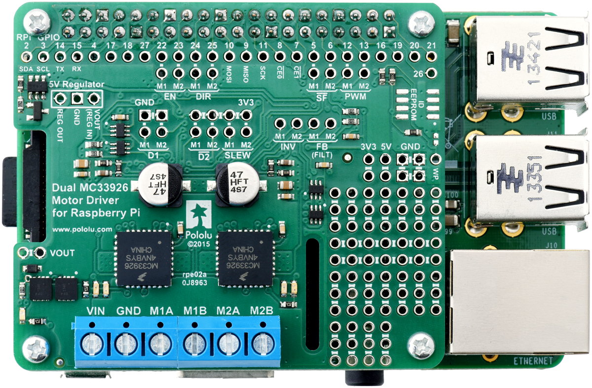
This motor driver board is an add-on for the all Raspberry Pi having the 40 pins GPIO that lets you easily control a pair of bidirectional, brushed DC motors. The expansion board uses two Freescale MC33926 motor drivers that operates from 5 to 28 V. The motor drivers can deliver a continuous 3 A per channel (up to 5 A per channel for a few seconds).
Other features like a reverse battery protection circuit and logic gates that reduce the number of I/O pins required to control the driver ICs effectively.
The board matches the Raspberry Pi HAT (Hardware Attached on Top) mechanical specification, although it does not conform to the full HAT specifications due to the lack of an ID EEPROM.
We also have a similar dual MC33926 breakout for Arduinos and Arduino-compatible boards. For a smaller, lower power, and lower cost alternative, consider the DRV8835 Dual Motor Driver for Raspberry Pi.
Features
- Wide operating voltage range: 5 V to 28 V
- Output current: 3 A continuous (5 A peak) per motor
- PWM operation up to 20 kHz, which is ultrasonic and allows for quieter motor operation
- Motor indicator LEDs show what the outputs are doing even when no motor is connected
- Board can optionally power the Raspberry Pi base directly through added regulator (not included)
- Python library makes it easy to get started using this board as a motor driver expansion board
- GPIO pin mappings can be customized if the default mappings are not convenient
- Remaining motor driver pins are exposed for advanced use
- Reverse-voltage protection on motor supply
- Prototyping space for easier/cleaner construction of custom circuits
- Pololu Dual MC33926 Motor Driver for Raspberry Pi schematic diagram (378k pdf).
Robust MC33926 drivers:
- Transient operation (< 500 ms) up to 40 V
- Internal peak-current limiting gracefully reduces the output power if the current or temperature get too high
- Under-voltage shutdown
- Output short-to-ground and short-to-Vcc protection
- MC33296 datasheet
Content
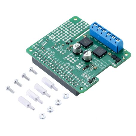
For each order, you will receive the board fully populated with its SMD components with a female header and terminal blocks included and soldered on the PCB.
The product also incluces 4 x M2.5 spacers (11mm length) spacers, screws and nuts to maintain the hat on the Raspberry-Pi.
The Raspberry-Pi, motors and power pack is not included!
Using the motor driver
This section explains how to use the dual MC33926 motor driver add-on board and provides some basic information about the motor driver pins to help get you started. However, we strongly encourage you to consult the MC33296 datasheet (1MB pdf) for detailed pin descriptions, truth tables, and electrical characteristics. This expansion board is essentially a breakout board for two MC33926 motor driver ICs with additional logic circuitry to simplify the motor control, so the datasheet is your best resource for answering questions not covered here.
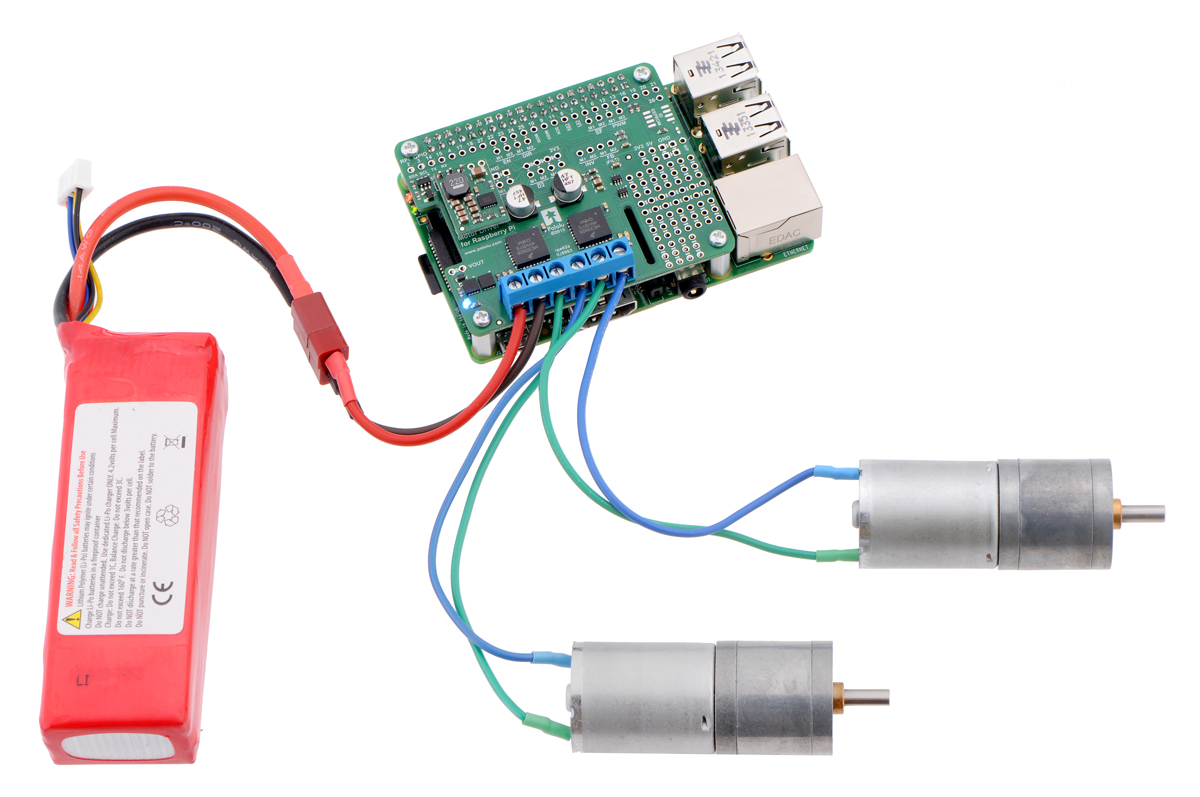
In the board’s default state, the motor driver outputs and the Raspberry Pi are powered separately, though they share a common ground and the board’s 3.3 V logic supply is provided by the Raspberry Pi. When used this way, the Raspberry Pi must be powered via its USB Micro-B receptacle, and the motor driver board must be supplied with 5 V to 28 V through its large VIN and GND pads. However, the motor driver board provides a set of three through-holes where you can conveniently connect an appropriate voltage regulator, allowing the motor supply to also power the Raspberry Pi (see the Powering the Raspberry Pi from the motor driver board section below).
A reverse-voltage protection circuit helps prevent damage to the board in case the motor power supply is connected backward. The reverse-protected input voltage can be accessed for use in other circuits through the two pins labeled VOUT on the left side of the board.
The board includes logic gates that enable drive/brake operation of the MC33926 drivers with only two control pins per motor (PWM and direction). As drive/brake operation usually provides a more linear relationship between PWM duty cycle and motor speed than drive/coast operation, we generally recommend using drive/brake operation when possible.
Default pin mappings
This table shows how the Raspberry Pi’s GPIO pins are used to interface with the motor drivers:
| RPi GPIO | Motor driver pin | Description |
|---|---|---|
| 5 | Motor 1 SF | Status flag output: When the driver is functioning normally, this pin should be pulled high by the Raspberry Pi. In the event of a driver fault , the driver IC drives SF low. If either of the disable pins (D1 or D2) is disabling the outputs, SF will also be low. |
| 6 | Motor 2 SF | see GPIO 5 description |
| 12 | Motor 1 PWM | Motor speed input: A PWM (pulse-width modulation) signal on this pin corresponds to a PWM output on the corresponding driver’s motor outputs. When this pin is low, the motor brakes low. When it is high, the motor is on. The maximum allowed PWM frequency is 20 kHz. |
| 13 | Motor 2 PWM | see GPIO 12 description |
| 22 | Motor 1 EN | Enable input: This pin is internally pulled low, putting the motor driver IC into a low-current sleep mode and disabling the motor outputs (setting them to high impedance). EN must be driven high to enable the motor driver. |
| 23 | Motor 2 EN | see GPIO 22 description |
| 24 | Motor 1 EN | Motor direction input: When DIR is low, motor current flows from output A to output B; when DIR is high, current flows from B to A. |
| 25 | Motor 2 EN | see GPIO 24 description |
Remapping pins
All of the Raspberry Pi’s GPIO pins are broken out along a row of numbered through-holes just below the 40-pin GPIO connector. Each GPIO pin used by the board is connected from this row to the corresponding motor driver pin by a trace on the underside of the board spanning the pair of holes. If you want to remap one of these motor driver pins, you can cut its trace with a knife and then run a wire from the lower hole to a new GPIO pin.
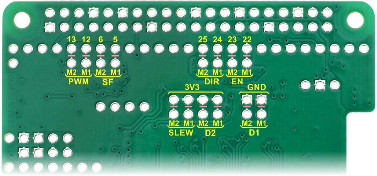
Note that the default pin mappings were chosen so that the Raspberry Pi’s default GPIO pull-ups and pull-downs match the direction the motor driver pins are or should be pulled (up for SF, down for others); if you remap the motor driver pins without paying attention to this, you might encounter issues with pins being pulled the wrong way. See the Raspberry Pi documentation for more about the default GPIO states.
Powering the Pi from the motor driver
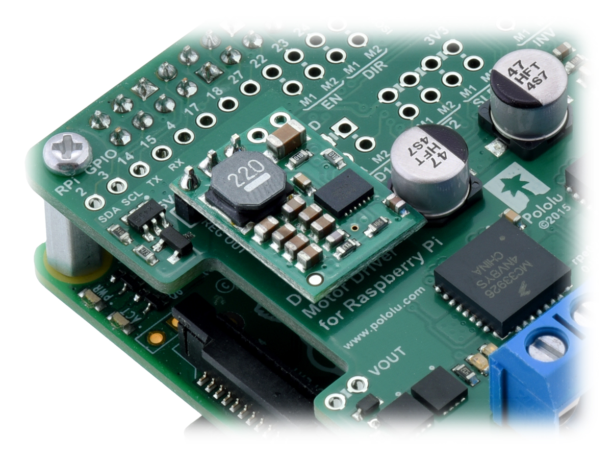
On the left side of the expansion board is a set of three pins surrounded by a box labeled “5V Regulator”. The “VOUT (REG IN)” pin provides access to the driver board’s motor supply voltage after reverse-voltage protection, while the “REG OUT” pin is connected to the Raspberry Pi’s 5V power rail through an ideal diode circuit. If a suitable voltage regulator is connected to these three pins, it can generate 5 V to power the Raspberry Pi from the board’s motor supply voltage. We suggest using our D24V5F5 or D24V10F5 switching step-down regulators, which work at input voltages up to the 28 V maximum of the MC33926 and can supply up to 500 mA or 1 A of current, respectively, to the Raspberry Pi.
When adding a voltage regulator to the motor driver board, take care to orient it correctly: note that the motor driver board’s “VOUT (REG IN)” pin should connect to the regulator’s VIN pin, while the regulator’s VOUT pin should connect to the motor driver board’s “REG OUT” pin.
There are a few considerations to keep in mind when “back-powering” the Raspberry Pi through a voltage regulator in this way:
- Your motor power supply must be an acceptable voltage for both the regulator and the MC33926 driver ICs.
- The regulator should be able to handle the power requirements of the Raspberry Pi. The Model B+ typically uses a few hundred milliamps at 5 V, although its current draw can exceed 1 A if it is also supplying power to USB devices and other peripherals. While a linear regulator like a 7805 might fit in the regulator mounting location, it could generate excessive heat or shut down at higher input voltages and output currents. We recommend using a switching regulator like the ones mentioned above.
The ideal diode circuit makes it safe to have a different power supply connected to the Raspberry Pi through its USB Micro-B receptacle while the motor driver add-on and regulator are connected and powered.
Real-world power dissipation considerations
Each MC33926 motor driver IC has a maximum continuous current rating of 5 A. However, the actual current it can deliver depends on how well you can keep it cool. The motor driver board is designed to draw heat out of the motor driver chips, but performance can be improved by adding heat sinks.
Unlike many other H-bridges, the MC33926 has a feature that allows it to gracefully reduce current as the current exceeds 5 A or as the chip temperature approaches its limit. This means that if you push the chip close to its limit, you will see less power to the motor, but it might allow you to avoid a complete shutdown.
We tested this motor driver board at room temperature with no forced air flow or heat sinks. In our tests, the board was able to deliver 5 A to both channels simultaneously for about 10 s before the thermal protection started reducing the current. The board delivered 4 A on both channels for about 40 s, and at 3 A it was able to operate continuously for over 10 minutes without triggering current limiting or thermal protection.
Our tests were conducted at 100% duty cycle; PWMing the motor will introduce additional heating proportional to the frequency.
Burn conditions
This product can get hot enough to burn you long before the chip overheats. Take care when handling this product and other components connected to it.